In contrast to petrol engines, injection systems in diesel engines operate with high system pressures. Fuel pumps, including the control periphery, are fundamentally different from their "petrol" counterparts. In technical terms, diesel engines are divided into in-line fuel injection pumps, plunger distributor fuel pumps, Common Rail systems and "pump-nozzle" systems. Under the hoods of both Mondeos with diesel engines, plunger distributor fuel pumps (Bosch VP30/66 kW/90 hp) directly feed fuel into the combustion chambers.; Bosch VP44/85 kW/115 hp) via pressure lines and through six-hole injectors. The fuel pump in the DuraTorg is driven by a duplex chain from the crankshaft.
Distribution fuel injection pump
Fuel supply and removal are carried out separately.
 |
|
1 - Feed pipeline,
|
8 — Connecting the drain pipe (only for engines with 90 hp),
|
The electronic pump control unit (PCU) is located on the top side of the pump. It uses the information from the steering angle sensor and the transmission control unit (PCM) and processes it to generate control signals for the high-pressure solenoid valve and the fuel injection start control system.
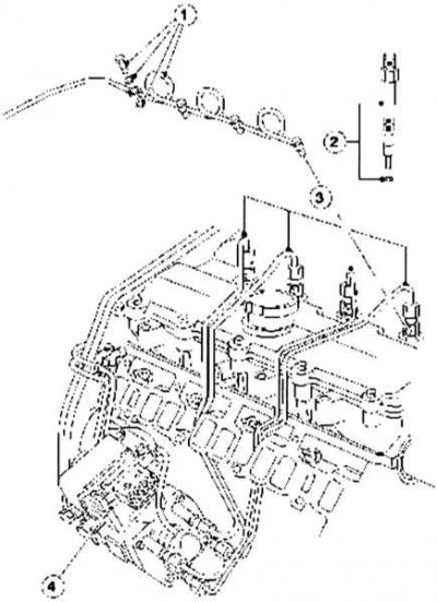
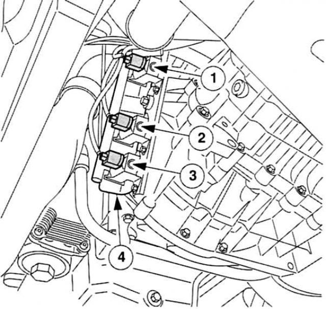
Equal lengths – fuel supply lines to injectors
Fuel is supplied to the injectors via pressure pipes of equal length. The nozzles are connected with clamping screws to the cylinder head. Copper sealing rings protect their ends from direct contact with surrounding parts. Replacement of sealing washers is usually performed after each nozzle dismantling.
Fuel supply
Fuel lines from the pump to the injectors.
 |
|
1 - Fuel drain line with connecting screw and seal,
|
3 - High pressure injection lines,
|
The Mondeo injectors are of a relatively thin design (pin injector). The injection direction of the six holes is oriented approximately to the center of a specially profiled combustion chamber cavity in the piston inside the cylinder. The 85 kW engine uses different injector options compared to the 66 kW engine. The injectors are calibrated differently, which results in different fuel flow rates.
Electronics and mechanics
Ford's 2.0-litre DuraTorg DI engines work with modern control technology. Their powertrain control units (PCMs) use a 32-bit bus and a CAN bus for data transfer.
 |
|
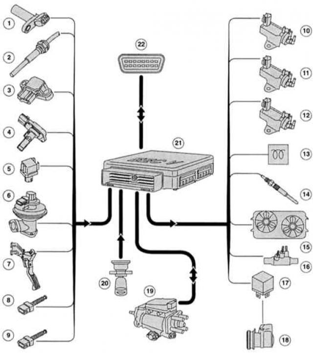
1 — Crankshaft position sensor (CPS),
|
12 — Boost pressure solenoid valve (only in 85 kW),
|
In detail – control of the injection system DuraTorg-DI
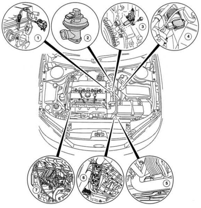
Sensors and actuators under the bonnet of the Mondeo engine with DuraTorg-DI 85 kW
 |
|
| 1 — SNT sensor,
2 — EGR valve, 3 — SKR sensor, 4 — MAF sensor, |
5 — T-MAP sensor,
|
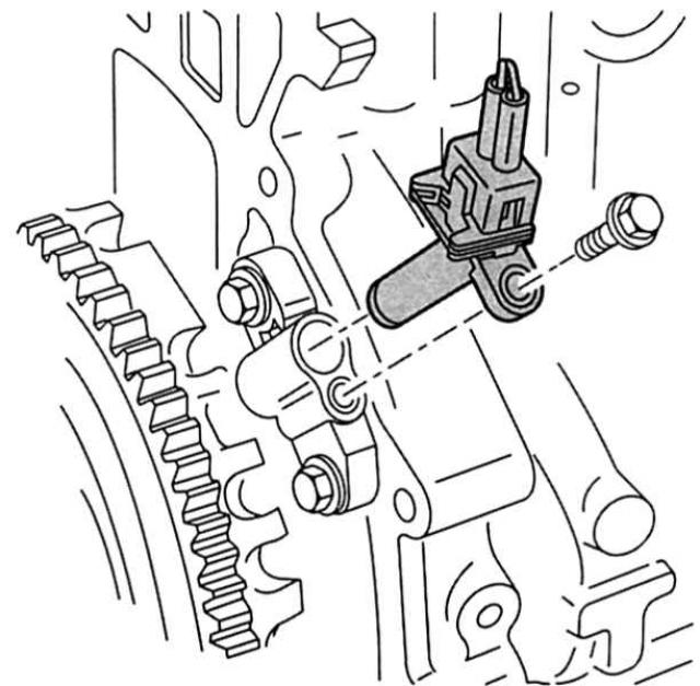 Direction of movement on the right: CKP sensor on the engine cylinder block flange. |
Transmission control unit (PCM/PATS integrated): The "central director's console" of the DuraTorg-DI engine management system is located on the side behind the side trim in the front right footwell. An on-board computer with 104 codes processes the current volume of data from various engine areas and compares them with fixed, factory-set parameters. For system analysis, Ford stations use exclusively the WDS diagnostic tool. It is connected via the 16-pin diagnostic connector (DLC) in the engine compartment.
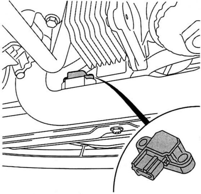
Cylinder Head Temperature Sensor (CHT): The CHT sensor is located on the transmission side of the cylinder head. It does not measure coolant temperature as is typical in older Ford engines, but the actual temperature of the cylinder head. Its signals influence injection volume, injection start, idle speed, glow plug control, EGR system, as well as coolant temperature indication and radiator fan control.
Crankshaft position sensor (CPS): The CPS sensor inductively registers the precise angular position of the crankshaft, as well as the current engine speed. Its signals are significant for the volume of the injected combustible mixture and the start of injection. The sensor is located on the side of the gearbox flange.
Exhaust gas recirculation sensor with valve (EGR/66 kW engine only): This position sensor provides the PCM with information about the current position of the EGR valve. It forms a separate component with the valve.
Manifold Absolute Pressure (MAP) Sensor with Intake Air Temperature (IAT) Sensor: It is located in the intake manifold between the charge air cooler and the intake manifold and performs the function of the MAP sensor and the intake air temperature sensor from its housing. The T-MAP sensor minimizes the power loss that occurs when driving on mountainous terrain and inclined road sections by instantly establishing the current operating condition of the engine at idle and full load. The measured value is the barometric pressure in the intake manifold. This data is recorded and processed by the PCM as a reference pressure for the corresponding intake manifold pressure under various load conditions.
To take into account the influence of temperature on the density of the boost air, the IAT sensor records the temperature of the boost air. Its signals are used by the PCM to obtain correction parameters when calculating the boost pressure. In this combination, the T-MAP sensor provides information to the PCM, on the basis of which the volume of air mass injected into the engine is calculated. All this also affects the amount of fuel injected and the EGR system.
 In double packaging: T-MAP sensor with built-in IAT sensor. |
Exclusively for 85 kW engine
The 85 kW variant uses the MAP signal in addition to controlling the boost pressure in the variable turbocharger. As soon as the actual measured value deviates from the value specified by the characteristic curve in the PCM, the PCM regulates the boost pressure via the corresponding electromagnetic valve.
Mass Air Flow (MAF) Sensor: The MAF sensor works on the hot wire principle. It is "inserted" into the air duct behind the air filter and primarily controls the EGR system.
Accelerator Pedal Position Sensor (APP): In order to vary engine power in accordance with the accelerator pedal position, the PCM uses the position data of the APP sensor. In principle, this sensor works similarly to a potentiometer, which measures the angular movements of the accelerator pedal via three sliding contacts. If two contacts fail, the engine only runs at increased idle speed. The APP sensor has an idle switch and a foot switch built into it. The PCM compares the signal from the idle switch with the signal from the potentiometer for plausibility.
Ambient air pressure sensor (BARO/85 kW engine only): The sensor is located in the passenger compartment, in the left bracket of the A-pillar reinforcement, behind the instrument panel. To avoid black smoke, it supplies the PCM with the current values of the prevailing ambient air pressure. Based on the signals sent, the on-board computer adjusts the boost pressure and the actual injection volume.
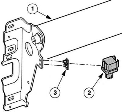 Attached to the instrument panel: Ambient air pressure sensor. 1 - Reinforcing element on the front pillar,
|
Brake Light and Brake Pedal Switch (BPS): The signal from the brake light switch turns on the brake lights and "checks" the APP sensor (plausibility check): during any braking process, the engine speed automatically drops to idle speed.
Mondeo with cruise control
In order not to stop the speed control system even with a "negligible" pressure on the brake pedal, a VRR switch with a long trip path comes to the fore. First, its signal goes to the on-board computer, which takes the speed control system out of the "game".
Clutch Pedal Position (CPP) Switch: This component signals the PCM whether the clutch is present or not. When the clutch pedal is depressed, the amount of fuel injected is reduced briefly to avoid engine jerking.
Mondeo with cruise control
In combination with the cruise control system, a second CPP switch is installed. Its contacts are connected to ground via the brake lights. In the resting position, the contacts are closed. Only when the clutch pedal is pressed does the switch open, causing the cruise control system to pause its operation.
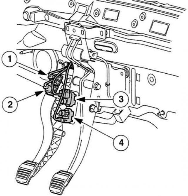 Communicate with RSM: VRR and SRR switches. |
Exhaust gas recirculation solenoid valve (EGR): The EGR valve mixes the fresh air drawn in with a portion of the exhaust gas. This reduces the nitrogen oxide content of the exhaust gas. The mixing process is controlled by the PCM: the solenoid valve converts its clock signals into a precisely defined control vacuum for the mechanically operated EGR valve.
Boost pressure solenoid valve (85 kW engine only): In order to optimally match the turbocharger boost pressure to the engine load status, the 85 kW engine does not have a supercharger with rigid guide vanes and bypass control, but a version with adjustable vanes. In order to ensure that these vanes are always in a certain position, depending on the engine load status, the boost pressure solenoid valve receives clock signals with the corresponding spatial parameter characteristic PCM. It converts the electrical clock signals into a specified control underpressure, which influences the low-pressure component for controlling the boost pressure.
Intake manifold flap electromagnetic valve: As soon as the engine stops, the PCM sends a corresponding signal to the intake manifold flap electromagnetic valve. Based on this, the valve acts according to the vacuum dose on the intake manifold flap and closes it for a few seconds.
 Shoulder to shoulder: 1 — Boost pressure solenoid valve (only in 85 kW engine),
|
Draining back to fuel tank - excess fuel
In terms of fuel quantity, it can be said that in DuraTorg-DI injection systems, more fuel is constantly circulating than is actually necessary. The injectors also do not inject the entire amount of fuel into the combustion chambers: the excess fuel is intended, among other things, to lubricate and cool the moving parts of the fuel pump and injectors.
The DuraTorg-DI Mondeo engine does, however, have a function that prevents complete emptying and thus "dry" operation of the system. As soon as the diesel fuel reserve reaches two percent, the RCM sets the fuel pump to zero supply. Advantage: it is usually necessary to "ventilate" the Mondeo only after replacing the fuel pump, otherwise the starter will do this for you during the long starting period.
In order for the fuel to "travel" through the system when the engine is running, diesel engines have feed and return lines. The injectors are also integrated into them: they have a return pipe and are in contact with each other via a hose line (oil return pipe). From the right injector relative to the direction of movement (cylinder 1), the fuel flows through the return pipe back to the fuel tank. The return hole of the injector of the fourth cylinder is sealed with a stopper according to this principle.
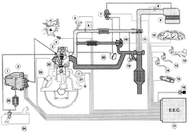
Engine control system
 |
|
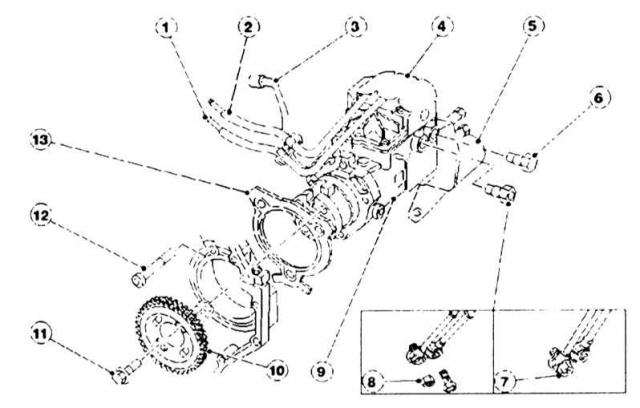
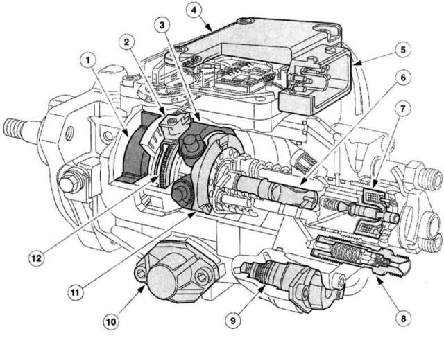
1 — Bosch VP-30 fuel distribution pump,
|
15 — Diagnostic connector (DLC),
|
Engine supply – this is how fuel gets to the injectors
The fuel pump pumps diesel fuel from the tank through the fuel filter to the high-pressure fuel pump via a closed pipeline system (supply and return pipelines). In existing distribution high-pressure fuel pumps, the fuel pump is operated by a vane pump. It is located in a round hole directly in the pump housing. Since this is a suction pump and compressor, the same pump also transports diesel fuel to the distribution high-pressure fuel pump's own compression zone. Only in the DuraTorg-DI 85 kW engine does the "diesel turnover" in the system support an additional electric fuel pump, the maximum volume here is 160 liters/hour.
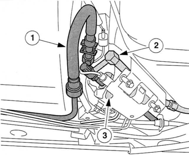 Additional fuel pump in the DuraTorg-DI 85 kW engine: 1 — Fuel line to the filter,
|
The "cleaner" before the high-pressure fuel pump is a fuel filter with a temperature-dependent control valve
The filter element is located in a place easily accessible for maintenance work at the right-hand shock absorber strut punch under the engine hood. A temperature-dependent control valve is located in the fuel return line. The advantage: excess diesel fuel now flows back into the fuel tank if its temperature is above 31°C. As soon as the fuel has cooled to 15°C, the valve feeds the excess fuel directly to the filter and thus maintains the fuel in a fluid state down to -35°C without "additional heating".
Together with the connecting pipes, the control valve forms a separate unit. Disadvantage: in service centers, it is necessary to completely replace the valve together with the pipes. As, incidentally, and the fuel filter - it can neither be dehydrated nor washed: therefore, the valve should be replaced regularly, therefore, to be on the safe side from "water damage", take such a spare element with you on a trip and long trips on the southern plains.
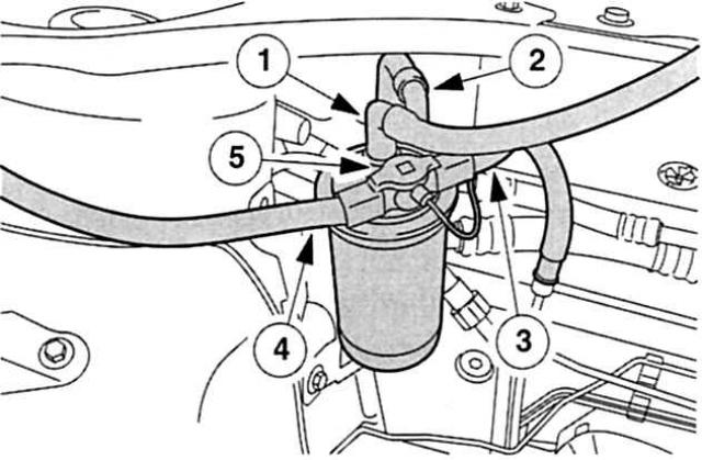 Cleaner with heat output: fuel filter before the injection pump. 1 - Supply pipeline to the electric pump,
|
Standard only in DuraTorg-DI 85 kW – fuel cooler
Compared to the VP 30, the VP 44 high-pressure fuel pump has a higher pressure. Naturally, this fact determines the increase in the temperature of the circulating diesel fuel. In order to ensure that the temperature level does not go beyond the limits even at high outside temperatures, part of the drain pipe is structurally designed as a "cold pipe". It cools the flowing fuel to 10 - 12°C.
 Required for DuraTorg-DI with 85 kW: fuel cooler under the vehicle floor. 1 - Internal cooling profile,
|
Increases hydraulic efficiency - high pressure fuel pump
The control unit (PCU) located on the top of the pump is used as a "command distributor" for all pump functions and is in "electrical" contact with the engine periphery and the accelerator pedal. The Bosch VP 30/VP 44 in the Mondeo are controlled by a high-pressure solenoid valve that loads the axial pistons. The valve operates in alternating mode, opening and closing strictly according to the parametric characteristic data stored in the PCU.
However, the start of the supply in the Mondeo is no longer commanded by a needle movable sensor - the "Go" command comes directly from the pump control unit and goes through the electromagnetic high-pressure sensor into the hydraulic system. The start of the fuel supply is determined by the moment of closing of the electromagnetic valve, the end of the supply is set by the moment of opening, and the volume of fuel is determined by the time interval during which the electromagnetic high-pressure valve is closed.
Distribution fuel injection pump VP 30
 |
|
1 - Vane pump,
|
7 — High pressure solenoid valve,
|
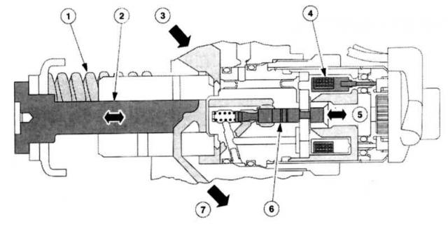
High pressure solenoid valve
 |
|
1 - Pressure spring,
|
5 - Direction of closing from opening,
|
Work distribution - control pulse sensor rotor
In order to ensure that each cylinder is fed in the correct sequence and at the right time, the pulse sensor rotor and the angle sensor act as a distributor. The pulse sensor rotor is connected directly to the engine drive shaft, and the angle sensor is firmly connected to the roller ring. As soon as the solenoid valve directs the injection controller, the roller ring rotates and thus the angle sensor to the "early" or "late" position. The pulse sensor rotor has a "gap between the teeth" for each cylinder. The desired "offer" for the angle sensor is that it scans the gap and sends the corresponding information to the PCU for subsequent use. These signals are the basis for the current angular position of the crankshaft, the current speed of the injection pump and the injection start control system.
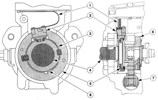
Rotor of the control pulse sensor and the angle sensor
 |
|
1 - Conductive film,
|
5 — Bearing rotating ring,
|
Makes a cold diesel engine quick - a device for starting a cold engine
The cold starter serves the same purpose as the automatic enrichment system for starting gasoline engines: both systems help cold engines in the transition phase. However, this is where the similarity ends. Although the cold starter sets its use depending on the prevailing temperatures, it does not, for example, reduce the air supply to the cylinders, but immediately sets the injection point in the "early" direction. This gives the atomized fuel more time to ignite in the compressed air and the pin glow plugs - the engine starts "more obediently and smoothly". In addition, the cold starter slightly increases the idle speed and - depending on the engine temperature - warms up for a certain period of time. This reduces the noise of the direct injection engine, improves the quality of the idle and reduces carbon emissions during the warm-up period.
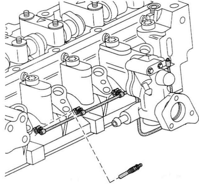 Heating a cold diesel engine: pin glow plugs in the cylinder head. |
Diesel fuel atomization – dual spring injectors
The injectors are the last resort of the diesel injection system. They spray fuel under high pressure into the combustion chamber. In order to minimize combustion noise and somewhat "tame" explosive pressure surges in the cylinders, the Mondeo injectors are equipped with two springs. The stroke of the first spring is set in such a way that the injector needle is already easily lifted from its seat at 222 - 230 bar. Thanks to this, a small amount of fuel enters the combustion chamber and ignites.
The purpose of the "pre-injection" is to gradually increase the combustion pressure, as it acts somewhat like a "wick" for a few milliseconds before the main injection, which occurs at 380 - 398 bar. In the Mondeo, these two injection processes "smoothly" merge into each other, the high-pressure solenoid valve receives a second control pulse for this. The injector needle then rises fully and injects the bulk of the fuel through six holes from the injection system into the combustion chamber. The air swirl caused by the "pre-injection" entrains fresh fuel particles and forms an almost homogeneous and easily ignited diesel-air mixture. The high spring elasticity acting on the injector needles prevents the combustion pressure from reacting with a backfire in the fuel system. Since the entire volume of fuel is never injected, excess fuel flows - as already mentioned - through the return line back into the fuel tank. The set time between the start of injection and the moment of ignition is 0.002 seconds. It is clear from this that even the slightest malfunction, such as a "sticking" needle, will throw the physically balanced combustion process out of balance. Loss of power, black smoke or loud "needle noise" (even with a warm engine) are unmistakable and "audible" signs that the diesel engine is in such a "state".
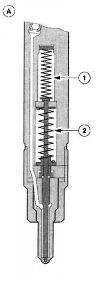 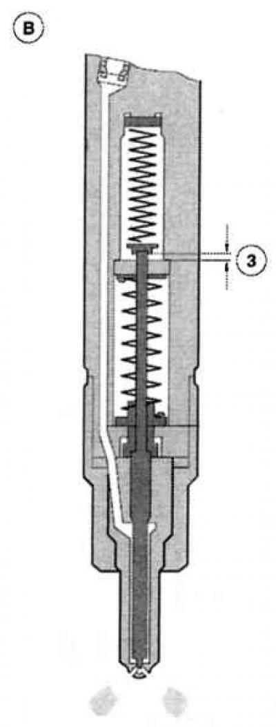 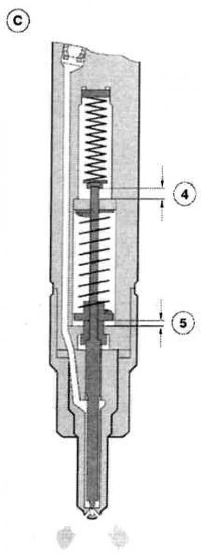 Double injection process: (A) the nozzle is closed, (B) Pre-injection, (C) main injection, 1 — Spring 1, 2 — Spring 2, 3 - Move 1, 4 - Move 1 move 2, 5 - Move 2. |
A case for experts – repair and correction of the diesel injection system
An experienced amateur can detect a single defective injector independently. To do this, listen to the engine "rumble" at idle speed, and briefly release the union nut of the pressure pipeline for all injectors in the row. If the rotation speed for the injector remains constant despite the pipeline being removed, then the atomizer or valve of the corresponding cylinder is considered defective. Damaged spray nozzles can also be recognized by the following symptoms:
- regular defects in glow plugs,
- constant black smoke from the exhaust system,
- increased consumption,
- frequently overheating engine,
- harsh combustion noises (loud needle movement),
- power loss,
- overspending.
If you have identified the above problems in your diesel Mondeo, find a car repair shop and report your problems to the specialists on site. They will be able to provide you with information on suitable countermeasures.
Disassembling the spray nozzle - leave this job to a specialist
Without a special inspection of the nozzle, you can only superficially judge its functioning. Naturally, you can find external damage or heavy contamination. Direct wear, of course, takes place inside the nozzle, on the needle, in the nozzle body or pressure spring. And here you have little opportunity to correct, because for this you need a special test device with which you can "squeeze" the nozzle, establish the "stream picture" and adjust the injection pressure. In most cases, it is better to completely replace the nozzle. If you are still going to disassemble this part, then its "insides" should not be left "open" on the workbench for a long time: the precision-machined surfaces of the nozzle needle and the nozzle body are very sensitive to dust and rust. Always install new nozzles with new sealing rings in the cylinder head. The tightening torque of the nozzle holder is 24 Nm.
[The original source of this article can be found at: Fordbook.ru]