Drain the oil from the engine.
Unscrew the oil filter.
Remove the high voltage wires.
Remove the spark plugs.
Remove the filler neck.
Disconnect the fuel supply system pipes and the vacuum pipes.
Remove the valve stem and push rods.
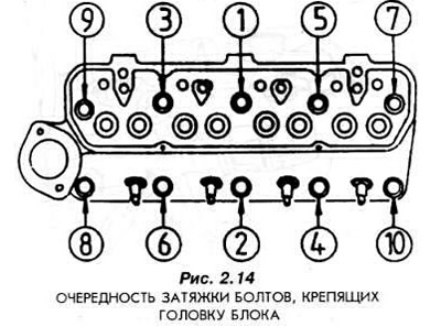
Unscrew the cylinder head mounting bolts in the reverse order to that shown in Fig. 2.14. Unscrew in several stages.
Remove the cylinder head. If necessary, loosen it with light blows of a plastic hammer. Under no circumstances should any tools be inserted between the cylinder head and the engine block.
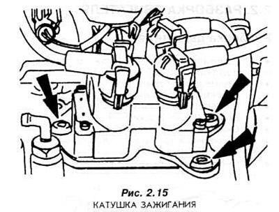
Unscrew the DIS ignition coil from the block (Fig. 2.15).
Remove the fuel pump if it is mounted to the engine.
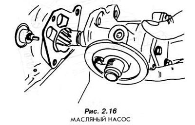
Remove the oil pump from the engine block (Fig. 2.16).
Remove the water pump pulley.
Remove the water pump.
Remove the water pump drive pulley from the crankshaft.
Remove the oil pan from below, having first unscrewed the mounting bolts.
Rotate the engine on the mounting stand 180°.
Remove the camshaft drive chain cover.
Remove the oil deflector from the crankshaft. Remember its installation position.
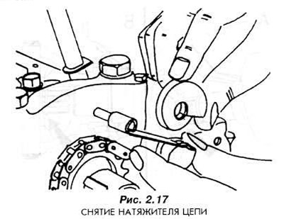
Remove the tensioner lever from the pin on the first crankshaft bearing cover. Remove the chain tensioner (Fig. 2.17).
Unlock the two bolts securing the timing gear to the camshaft. Remove these bolts.
Remove the sprocket together with the chain.
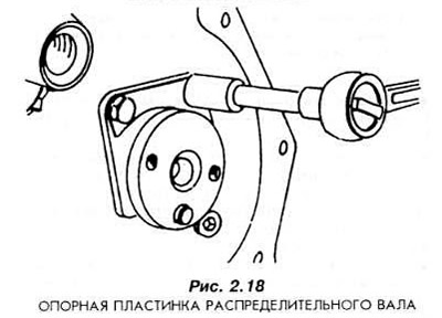
Unscrew the bolt securing the camshaft support plate (Fig. 2.18).
Carefully pull the camshaft out of the engine housing.
Remove the tappets from the engine housing. Store them in such a way that during assembly they are installed in the same holes from which they were removed. Do not mix up the installation locations of the tappets under any circumstances!
Remove the pulley from the crankshaft.
Install the pistons approximately halfway up the cylinders and clean the cylinder edges from any remaining burnt oil and carbon deposits. Be very careful not to damage the cylinder surfaces.
Unscrew the connecting rod bolts and remove the connecting rod lower head caps.
Remove the pistons with connecting rods upwards.
Remove the liners glued to the crankshaft journals. Without mixing them up, place them in the corresponding connecting rods together with the corresponding caps and bolts.
In several stages, unscrew the bolts securing the clutch housing to the flywheel.
Remove the flywheel.
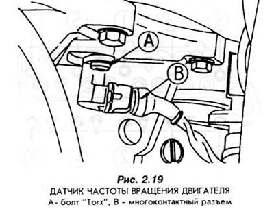
Remove the engine speed sensor (Fig. 2.19).
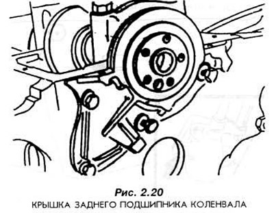
Unscrew the bolts securing the crankshaft rear bearing cover (Fig. 2.20).
Remove the crankshaft main bearing caps.
Remove the crankshaft from the engine housing. Remove the glued liners.
Degrease and clean all parts except the liners. The liners are used to evaluate the bearings during engine assembly. Therefore, they must be kept in an undamaged condition.
[For more information, please visit the website: FordBook]