To disassemble the engine, you will need a special tool: a setting gauge for adjusting the camshafts, an insert for a key with a multi-faceted engagement for loosening and tightening nuts. If it is necessary to remove the crankshaft or connecting rods, then a plastic Plastigage rod is needed to measure the clearances in the bearings.
When completely disassembling the engine, follow the following sequence (gearbox removed from the engine flanges):
Engines produced before May 1998.
- place the engine on the workbench taking into account the described preparatory work;
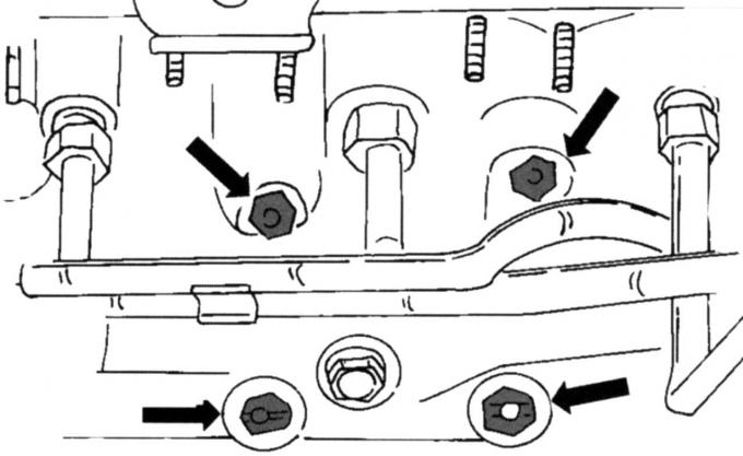
Fig. 40. Catalytic converter mounting locations
- on a 2-liter engine, unscrew the catalytic converter from the exhaust manifold (Fig. 40);
- Disconnect all multi-pin connectors (engine wiring harness, throttle control, camshaft position sensor); other plug connectors can be found on the ignition coil and suppression capacitor, and for the coolant temperature sensor (above the plug connector for the ignition coil). Disconnect the plug connector on the alternator;
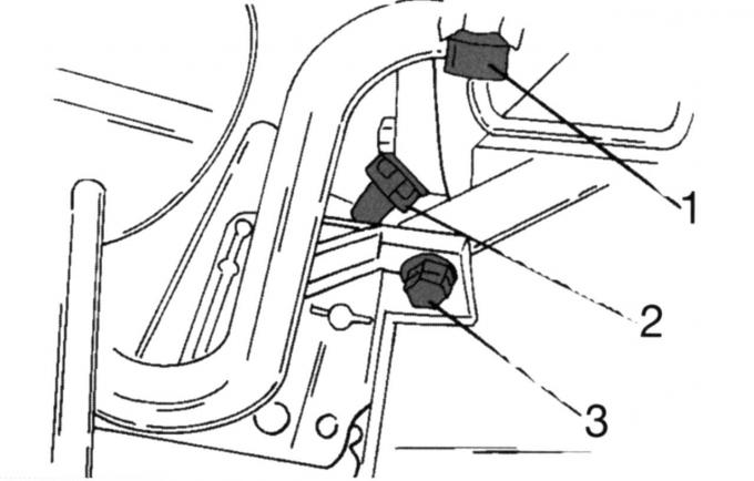
Fig. 41. Position of plug-in blocks: 1, 2 — plug-in blocks; 3 - screw
- remove multi-pin plugs 1 and 2 (Fig. 41) of the temperature sensor for the remote thermometer and the crankshaft position sensor, respectively. Loosen screw 3;
- unscrew the three screws and remove the thrust bearing of the drive shaft. In the immediate vicinity of it, unscrew the oil membrane switch;
- unscrew the main engine wiring harness from the intake manifold. It is secured in three places. Unscrew the alternator mounting screws and remove it. The belt roller located nearby can also be removed. After removing the alternator, remove the suspension bracket and unscrew the engine suspension bracket;
- remove the EGR valve and seal. Unscrew the Pulse-Air system fastening in this area;
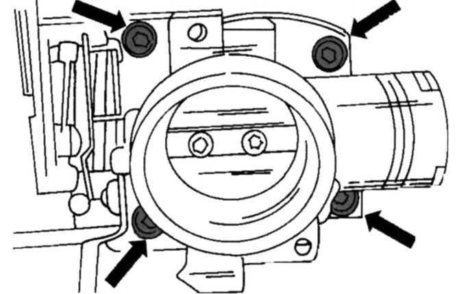
Fig. 42. Throttle body mounting locations
- unscrew the throttle body (Fig. 42);
- disconnect the engine ventilation hose from the intake manifold pipe and unscrew the four nuts and two manifold mounting screws;
- remove the intake manifold;
- install the engine on a mounting stand, drain the engine oil and unscrew the oil filter;
- remove the heat shield with the mount and the coolant hose with the pipe;
- unscrew the compressor consoles (if installed) and the auxiliary power steering pump;
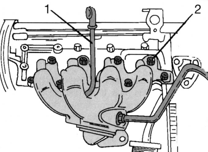
Fig. 43. Fastening the exhaust manifold on one side of the engine: 1 - oil dipstick; 2 - manifold mounting nuts
- remove the oil dipstick 1 (Fig. 43), unscrew the nine nuts 2 and carefully remove the exhaust manifold with the Pulse-Air system;
- remove the spark plug caps, unscrew the ignition coil holder (three screws) and the thermostat housing (three screws);
- remove the crankcase ventilation pipe, remove the three fan screws and take out the fan;
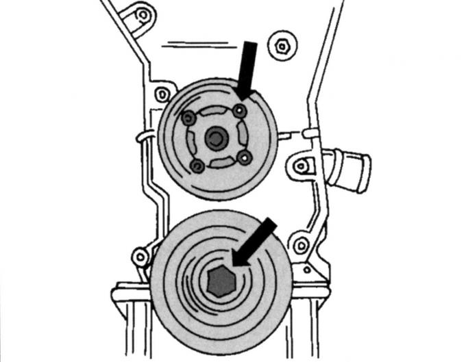
Fig. 44. Pulleys of the liquid pump and crankshaft
- remove the fluid pump and crankshaft pulley (Fig. 44). When unscrewing the latter, the crankshaft must be held from turning;
- unscrew the protective cover of the toothed drive belt on the front side;
- holding the flywheel from turning, unscrew the clutch. Remove the driven disk. Similarly, unscrew the driving disk of the automatic transmission torque converter;
- remove the spark plugs;
- remove the toothed drive belt as described below for this engine in the relevant subsection;
- remove the released crankshaft pinion. The outer side of the pinion disc is marked "FRONT". There is a thrust washer behind it. Remove it from the end of the crankshaft;
- remove both camshafts and the cylinder head;
- remove the cylinder head cover and seal;
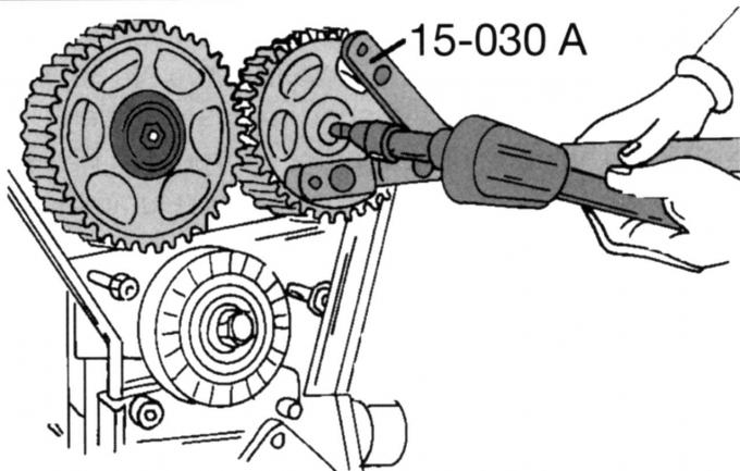
Fig. 45. Tool for holding camshaft gears
- loosen the screws securing the toothed pulleys of the camshafts. The camshafts will rotate, they must be held from turning (Fig. 45). If there is no special tool, insert a mandrel into one of the holes and carefully lock it against the cylinder head. Remove both toothed pulleys, marking their belonging;
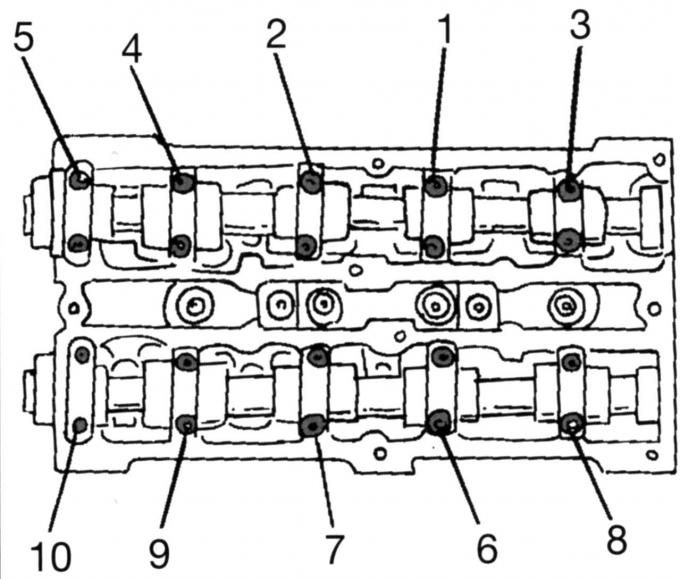
Fig. 46. Sequence of loosening the camshaft bearing caps
- remove the camshafts. To prevent the shafts from being deformed, loosen the bearing caps in a specific sequence (Fig. 46). Loosen the bearing cap nuts in the specified sequence by half a turn so that they are free and can be unscrewed by hand. Mark the caps and remove them one by one. Carefully remove both camshafts and remove the radial sealing rings;
- remove the hydraulic tappets one by one and set them aside in the order required for installation or mark them;
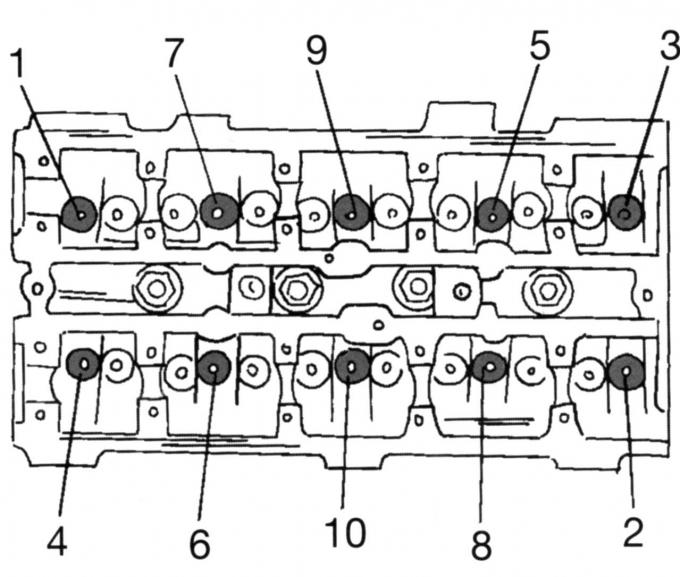
Fig. 47. Sequence of loosening the cylinder head mounting screws
- remove the cylinder head assembly. To do this, unscrew the screws in the sequence shown in Fig. 47. To do this, you will need a key with a multi-sided insert head so as not to damage the screw heads. After removing the dipstick tube, remove the cylinder head (if necessary, help with a rubber hammer) and place it on two wooden blocks;
- unscrew the liquid pump (four screws);
- align the engine so that the oil pan is at the bottom and unscrew it. This way, the oil sludge will remain in the bath and will not flow into the cylinder;
- from the back of the engine, unscrew the crankshaft position sensor holder and the cover with the oil sealing ring (four screws). The oil sealing ring can be removed from the cover immediately;
- unscrew the oil suction screen from the inside of the crankcase. The oil line shield is now accessible and can be removed after unscrewing four nuts;
- unscrew the six screws and remove the oil pump;
- turn the crankshaft (by the edge of the flywheel) so that all the pistons stop approximately in the middle of the working stroke, and with a scraper carefully scrape off the carbon deposits from the ring on the upper side of the cylinder holes, without damaging the cylinder channels;
- unscrew the bearing caps from the connecting rods one by one. Lightly hit the cap with a rubber hammer and remove it together with the bearing shell. Usually the caps and connecting rods are marked with numbers from 1 to 4, but you must check whether these numbers are visible. The cylinder number is respectively stamped on the connecting rod and the bearing cap in opposite places;
- push the pistons with connecting rods from below through the cylinders. Accordingly, two pistons should be at the bottom dead center (BDC) to facilitate removal. It is best to screw the bearing caps and liners back onto the corresponding connecting rod to hold them together;
- the flywheel is held in place by six screws and can be disconnected. When unscrewing the flywheel, the crankshaft must be locked. This is best done by wedging a wooden block into the inner part of the crankcase so that it is located between the crankshaft cheek and the crankcase wall, and the shaft is clamped;
- unscrew the crankshaft main bearing cap fastening screws, slightly loosening each screw;
- remove the screws and bearing caps with liners. Mark each cap and liners (e.g. with color marks) so that they can be reinstalled in their original place;
- carefully remove the crankshaft from the bearings and place it in a clean place;
- remove the bearing shells from the crankcase and mark them to avoid confusion, put them aside with the other bearing shells;
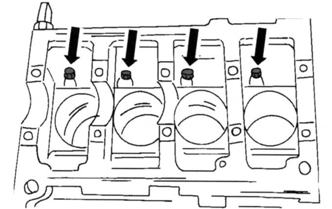
Fig. 48. Position of oil nozzles in the cylinder block
- in the places shown in Fig. 48, there are oil nozzles for cooling the piston. They can also be removed;
Engines produced since May 1998.
- after completing the described preparatory work, install the engine on the workbench;
- Disconnect the wire plugs from the camshaft position and coolant temperature sensors. Disconnect the wires from the ignition coil;
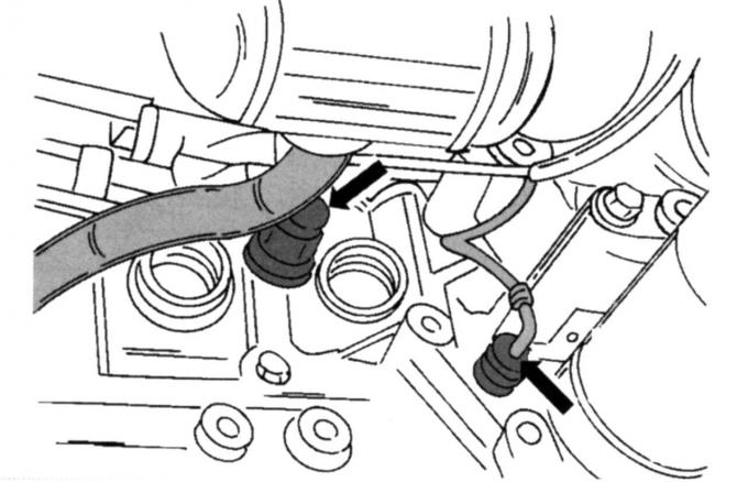
Fig. 49. Location of plug connectors for oil pressure switch and fuel knock sensor
- disconnect the plugs from the oil pressure switch and the fuel knock sensor (Fig. 49);
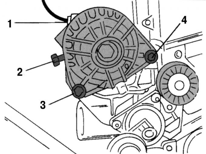
Fig. 50. Generator mounting: 1 — plug; 2 — cable; 3, 4 - screws
- remove the generator. To do this, disconnect the plug 1 (Fig. 50), the current-carrying cable 2, remove the screw 4 and unscrew the screw 3;
- disconnect the plug from the magnetic valve installed on the intake manifold, unscrew the seven screws and two nuts and remove the intake manifold;
- remove the generator support bracket, oil filter, knock sensor and oil pressure switch on the intake side of the engine;
- unscrew the console at the front for the auxiliary power steering pump and air conditioning compressor (if installed);
- remove the crankcase ventilation parts. To do this, remove and take out three screws;
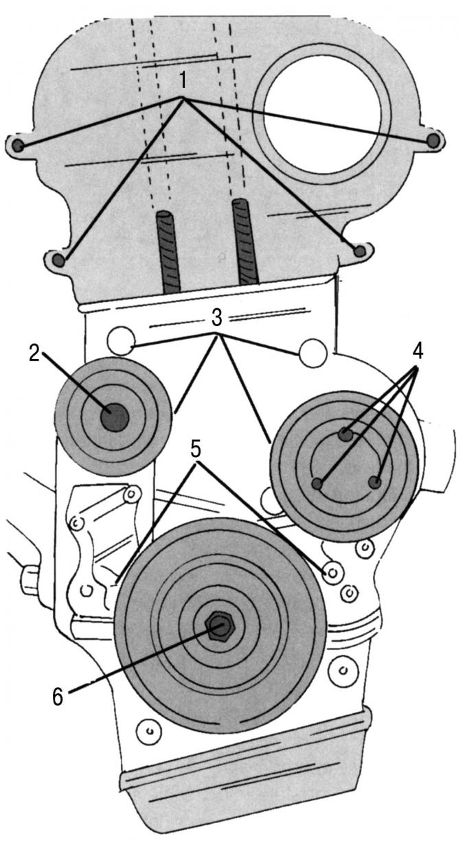
Fig. 51. Removing parts on the front side of the engine: 1 - top cover; 2 - running roller; 3 - middle cover; 4 - water pump pulley; 5 — lid; 6 — crankshaft pulley
- remove the toothed drive belt protective cover. Before removing the lower cover, remove the liquid pump pulley 4 (Fig. 51), the running roller 2 of the poly V-belt and the middle cover 3 together with the engine mount support. After that, remove the upper cover 1, the crankshaft belt pulley 6 and the cover 5. To unscrew the pulley screw, hold the crankshaft from turning;
- remove the cap from the cylinder head. First, disconnect the high-voltage wires from the spark plugs. Do not pull the cables, but the plugs. Unscrew the cover screws at the top of the engine and unscrew the spark plugs;
- remove the toothed drive belt as described in the relevant subsection for this engine and unscrew the liquid pump. The belt drive may be equipped with a running roller for the toothed drive belt;
- loosen the screws securing both camshaft toothed pulleys, holding the shafts from turning. The clamp shown in Fig. 45 is best suited for this purpose. Otherwise, insert a drift into one of the holes and carefully lock it against the cylinder head. Remove both pulleys, marking their belonging;
- remove the camshafts. To avoid deforming the shafts, loosen the bearing caps in a specific sequence (see Fig. 46). Accordingly, loosen the bearing cap nuts in the specified sequence by half a turn so that they can be unscrewed by hand. Mark the caps and remove them one by one. Carefully remove both camshafts and remove the radial sealing rings;
- remove the plate tappets one by one and set them aside in the sequence required for installation, or mark them accordingly;
- remove the cylinder head assembly. To do this, unscrew the screws in the sequence shown in Fig. 47. To do this, you will need a key with a multi-sided insert head so as not to damage the screw heads. After removing the dipstick tube, remove the cylinder head (if necessary, help with a rubber hammer) and place it on two wooden blocks;
Note: The cylinder head bolts on these engines can only be used twice, so mark them with one or two punch marks. If the bolts already have two punch marks, they have already been used twice.
- align the engine so that the oil pan is at the bottom and unscrew the pan. This will keep the oil sludge in the bath and will not drain into the cylinders.
- from the back of the engine, unscrew the crankshaft position sensor holder and the cover with the oil sealing ring (four screws). The oil sealing ring can be removed from the cover immediately;
- unscrew the oil suction sieve from the inside of the crankcase. This separates the lower half of the crankcase from the cylinder block;
- unscrew the six screws and remove the oil pump;
- turn the crankshaft (by the edge of the flywheel) so that all the pistons stop approximately in the middle of the working stroke, and with a scraper carefully scrape off the carbon deposits from the ring on the upper side of the cylinder holes, without damaging the cylinder channels;
- unscrew the bearing caps from the connecting rods one by one. Lightly hit the cap with a rubber hammer and remove the cap together with the bearing shell. Usually the caps and connecting rods are marked with numbers from 1 to 4, be sure to check whether these inscriptions are visible. The cylinder number is respectively stamped on the connecting rod and the bearing cap;
- push the pistons with connecting rods through the cylinders from below. Two pistons should be at BDC to facilitate removal. It is best to screw the bearing caps and liners back onto the corresponding connecting rod to hold them together;
- Disengage the clutch;
- the flywheel is held in place by six screws, it can be unscrewed by locking the crankshaft. This is best done by wedging a wooden block into the inner part of the crankcase so that it is between the crankshaft cheek and the crankcase wall, and the shaft should be clamped;
- unscrew the crankshaft main bearing cap fastening screws, slightly loosening each screw;
- remove the screws and bearing caps with half bearing shells. Mark each cap and shell in a suitable way (e.g. with color marks) so that they can be installed in their original location;
- carefully remove the crankshaft from the bearings and place it in a clean place;
- remove the bearing shells located in the crankcase and mark them accordingly;
- to avoid confusion, put them aside with other bearing shells.