V6 engine
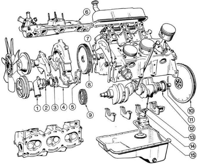
1 - thermostat housing, 2 - thermostat, 3 - water pump, 4 - timing cover, 5 - bypass hose fitting, 6 - intake manifold, 7 - camshaft thrust plate, 8 - camshaft gear, 9 - crankshaft gear, 10 - flywheel, 11 - bearing, 12 - rear sealing ring, 13 - oil pump drive, 14 - main bearing cap, 15 - oil pump
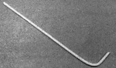
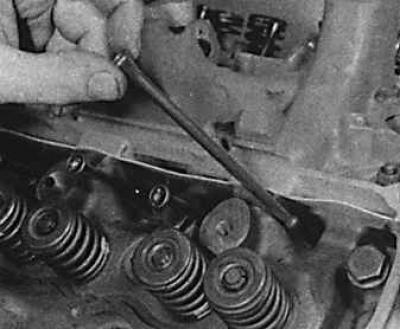
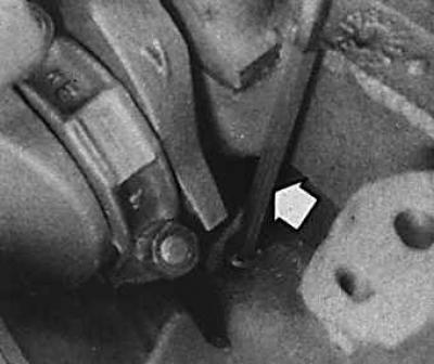
Bent wire for extracting valve lifters
If possible, install the engine on a stand; if not, install it in such a way that the engine cannot be damaged when unscrewing tightly tightened nuts and bolts.
Cleanliness is very important during disassembly to prevent contamination of the disassembled components. Before proceeding with disassembly, clean the outside of the engine with kerosene or, if heavily soiled with solvent.
In the absence of a special stand for disassembling the engine, disassemble it on a wooden stand. Do not dismantle directly on the concrete floor, as concrete particles will become a source of contamination.
When the parts are removed from the engine, wash them in kerosene. Never immerse parts with internal lubrication channels in kerosene, such parts should be thoroughly wiped with a cloth soaked in kerosene, and the lubrication channels should be cleaned with a wire rope.
It is recommended to store small parts in suitable containers, so that the parts will not be lost and will not have to be searched for during subsequent assembly.
When disassembling the engine, keep the old gaskets, they will serve as a model for the manufacture of gaskets, in the absence of new finished gaskets.
Although the parts listed below can be removed separately, ie. without removing the engine, it is recommended to remove them when dismantling the engine after the engine has been removed:
- carburetor or fuel injection system components;
- distributor;
- fuel pump;
- water pump;
- alternator;
- power steering pump (when disconnected from the system).
Attention! The disassembly of the carburetor engine is described. Disassembly of engines on models with fuel injection is carried out in a similar way, taking into account the fact that when removing parts of the fuel injection system, attention should be paid to the exact location of the parts so that they can subsequently be correctly installed in their original places.
1. Drain the oil into a suitable container (if it hasn't been done before).
2. Unscrew the oil filter using a belt or chain wrench.
3. Remove the dipstick to measure the oil level.
4. On some vehicle models, use a 37mm wrench to unscrew the special nut that secures the extension bracket to the oil cooler. Remove bracket with washers and O-ring. Unscrew the central sleeve and remove the oil cooler together with the gasket.
5. Remove clutch. Note installation position of clutch disc.
6. Remove engine support brackets.
7. Remove the power steering pump and drive belt.
8. To unscrew a bolt of fastening of a clamping flange of the distributor of ignition and to take the distributor from the block of cylinders.
9. Remove the two bolts securing the power steering pump drive belt idler pulley bracket to the top cover, and remove the bracket and pulley.
10. Loosen the alternator mounting bolts and lift the alternator, remove the fan belt. Remove the three bolts securing the alternator support bracket to the cylinder block and remove the alternator with bracket.
11. Remove fan and pulley from water pump.
12. Disconnect the fuel line from the carburetor and remove the crankcase ventilation valve (if installed) from the cylinder head cover.
13. Loosen the fastening clamps and disconnect the hose from the water outlet and the bypass hose from the thermostat housing.
14. Unscrew the four mounting bolts, remove the carburetor and intermediate flange from the intake manifold.
15. Unscrew the bolts of the cylinder head covers and remove the covers.
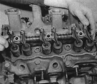 | 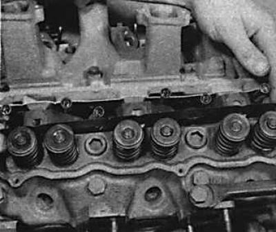 |
16. Unscrew the fixing bolts of the valve rocker axles and remove the axles (drawing on the left) and oil deflectors (drawing on the right). Pay attention to the direction of installation of the shields. Make marks on the axis of the rocker arms for subsequent installation in their original places.
17. Remove push rods. Put them to the corresponding axes of the valve rocker arms, for re-installation in their original places.
18. Remove the fixing bolts for the intake and exhaust manifolds and remove the manifolds. Because sealant is used when installing the intake manifold, it is necessary to use a screwdriver to remove the manifold, however, never place a screwdriver between the contact surfaces of the intake manifold and cylinder block.
19. Sequentially unscrew the cylinder head bolts; the order of unscrewing the bolts must be reverse to the order of their tightening.
20. Remove cylinder heads. If the head cannot be removed, it is necessary to break the integrity of the seal between the cylinder block and the head by shaking the head. If this does not help, you can try to release the head with sharp blows with a soft-faced hammer. Never hit the head directly with a metal hammer: this can destroy the fragile casting. It is also impossible to separate the head by inserting a screwdriver or a chisel between it and the cylinder block, since this can damage the mating surfaces of these parts.
21. Remove the cylinder head gaskets.
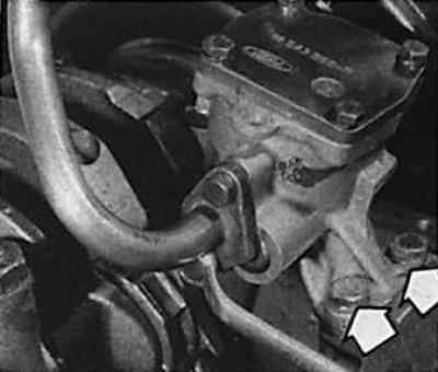
22. Remove the two bolts that secure the fuel pump to the block, then remove the pump, gasket, and linkage linkage.
23. Unscrew and remove the oil pressure sensor.
24. Unscrew the bolt that secures the crankshaft pulley and remove the pulley. If the pulley is attached to the vibration damper, also unscrew the central bolt of the damper.
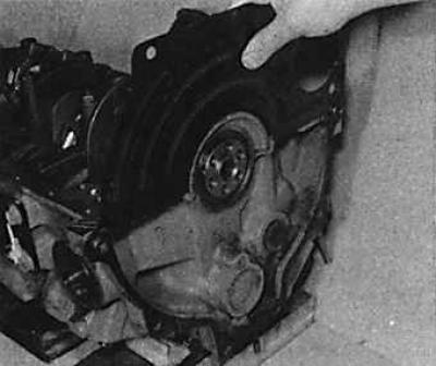
25. Mark the position of the flywheel in relation to the crankshaft so that it can be reinstalled in the same position later.
26. Block the flywheel, then unscrew the six bolts that secure the flywheel to the crankshaft, and remove the flywheel.
27. Remove the engine backplate.
 | 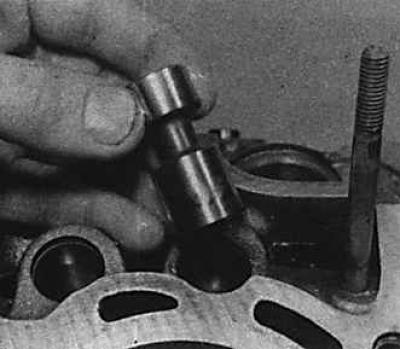 |
28. Install the motor on the end and using a bent copper wire (see fig. Bent wire for extracting valve lifters) remove the valve lifters. Lay the pushers against the corresponding pusher rods to be installed later in the original holes.
29. Remove the oil pan mounting bolts and remove the pan and pan gasket.
30. Unscrew the intake pipe from the oil pump and remove the gaskets.
 |  |
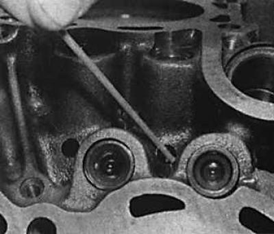
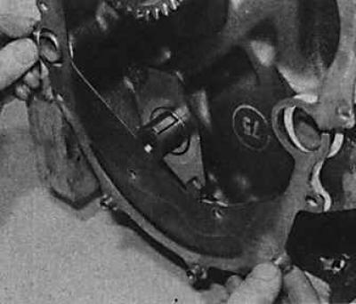
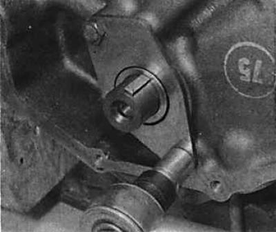
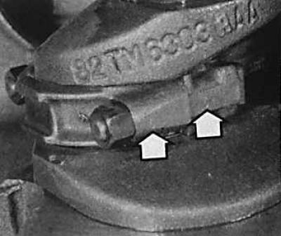
31. Unscrew two screws (indicated by arrows in the figure on the left) and remove the oil pump. Remove drive shaft (indicated by the arrow in the figure on the right) oil pump, paying attention to the installation position.
32. Remove the clutch housing cover.
33. Unscrew the rear pipe of the thermostat of the cooling system. Remove gasket.
34. Unscrew the bolts that secure the water pump to the timing gear cover and remove the water pump.
35. Unscrew the bolts of the thermostat housing, remove the housing and remove the thermostat. Disconnect the rear water pipe.
36. Unscrew the bolts that secure the timing gear cover to the front of the cylinder block and remove the cover.
37. Remove O-rings that cannot be reused.
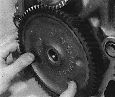
38. Unscrew the bolt that secures the camshaft gear to the camshaft and remove the gear.
39. Unscrew the fastening bolts of the front intermediate plate and remove the intermediate plate.
40. Unscrew the two fixing bolts of the camshaft thrust flange and remove the camshaft together with the thrust ring, then remove the leaf spring and gasket.
41. If necessary, remove the crankshaft gear using a conventional puller to remove.
 | 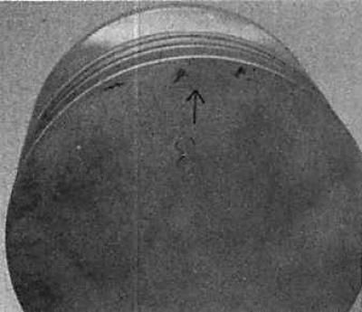 |
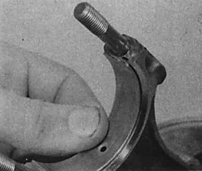
42. Check identification marks on connecting rod bearing caps and connecting rods (drawing on the left), to make sure that the caps match the connecting rods and subsequently install the groups of parts in their respective places. Piston bottoms are marked (arrows), pointing to the front (drawing on the right). The arrows on the piston crown must point towards the front of the engine.
43. Unscrew the nuts of the connecting rod caps and position on one side in the order in which they were removed.
44. Remove the connecting rod caps, arrange for storage in the appropriate order, paying attention to the direction of installation. Also make sure the liners are stored with the correct connecting rods unless they need to be replaced. If the connecting rod caps cannot be removed, lightly tap them with a soft-faced hammer.
45. To remove the liner, press it against the groove in the connecting rod and the cover, the liner will easily be removed.
46. Pushing with a hammer handle from below, remove the piston and connecting rod up from the cylinder.
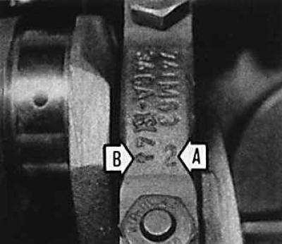
47. Check that the main bearings have identification marks to allow them to be placed in the correct positions during assembly. Bearing numbers are marked on the bearing caps (indicated by arrows A and B), and the arrow points to the front of the engine. It should be noted that on the 2.8 liter engine, the covers numbered 2 and 3 are attached with longer domed bolts.
48. Unscrew the mounting bolts and remove the main bearing caps and lower bearings; inserts should be stored with appropriate caps.
49. When removing the rear main bearing cap, remember that it also holds the crankshaft rear seal ring.
50. When removing the main bearing cap No. 3, pay attention to the location of the two thrust half rings.
51. Remove the crankshaft from the crankcase and remove the rear O-ring.
52. Remove the lower main bearing shells and No. 3 upper thrust washers from the crankcase and store them with their respective main bearing caps.
Visitor comments