Notes
- When you remove the wire from the battery, the memory of electronic storage devices is erased, so remember the radio code.
- Open the expansion tank cap only when the engine is cold.
- Disconnect the battery during operation.
- Cable bundles must be cut and replaced with new ones during installation.
- Loosen the right wheel nuts first (it needs to be removed later).
Pre-May 1998 production engines
To remove the cylinder head, perform the following operations:
- Remove the storage battery;
- place the front of the car on supports and unscrew the mudguard shield (nine screws);
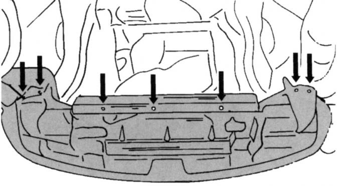
Pic. 52. Fixing the radiator lining
- unscrew the lining at the bottom of the radiator (pic. 52);
- drain the liquid from the cooling system after unscrewing the drain plug in the radiator (see relevant subsection);
- turn away the right forward wheel and remove facing on the inside of a wheel arch (two screws);
- Remove poly V-belt;
- on a 1.6- or 1.8-liter engine, remove the catalytic converter from the arched supports. To do this, loosen the clamping bracket and unscrew the arc;
- Disconnect the engine wiring harness and the evacuation line to the brake booster from the intake manifold pipe. The wiring is fastened with a quick-release constipation. Press it aside and remove the wiring. Remove the hose from the intake manifold;
- remove the plug from the oil pressure switch;
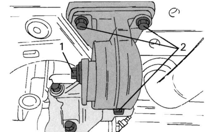
Pic. 53. Mounting the engine mount: 1, 2 - screws
- on a car with a manual transmission, loosen screws 1 and 2 by two turns (pic. 53);
- on a car with an automatic transmission, loosen the middle screw of the right anti-rotation stop by two turns. Do the same on the torque arm on the vibration damper and on the support;
- on all vehicles, disconnect the left stop from turning, but do not remove it;
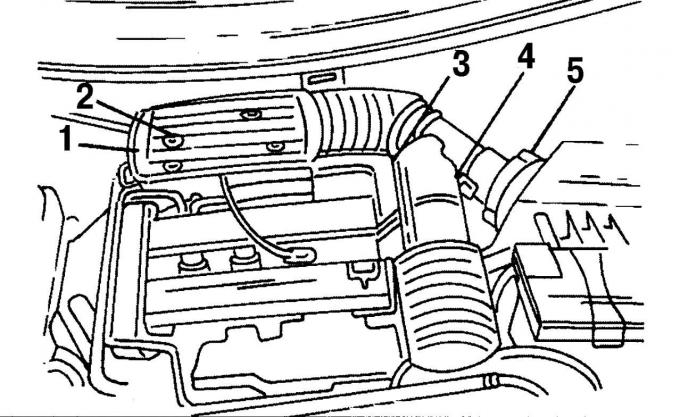
Pic. 22. Fixing the air intake pipes: 1 - mounting bolts, 2 - plug, 3 - plug, 4 - clamp, 5 - low pressure hose
- Completely remove the suction pipe. First remove the three screws 1 (see fig. 22). Then disconnect the plug 3 from the sensor, and on the same side remove the hose clamps 4. Disconnect at the place under the number «2» multi-pin connector for the intake air sensor. On the left side is a low pressure hose 5. Remove it;
- Remove the air filter. To do this, disconnect the ventilation hose between the filter and the cylinder head cover. Unhook the rubber ring on the right, remove the air filter from the mount and remove it;
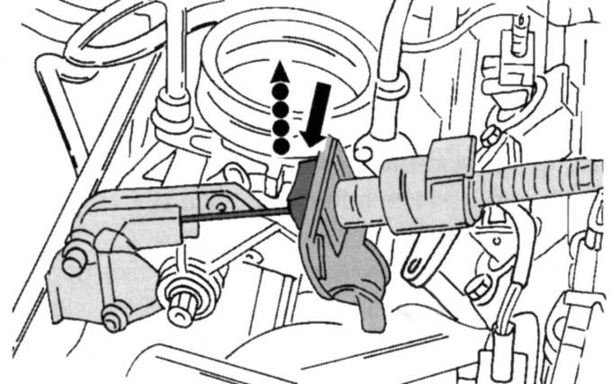
Pic. 54. Removing the throttle cable
- remove the throttle cable safety clip, disengage the throttle cable at the end of the lever and carefully pull the cable back (pic. 54);
- Disconnect the low pressure hoses from the intake manifold pipe;
- Remove the wire plug from the cylinder head wire harness and separate the wire harness from the intake manifold;
- disconnect the various low-pressure hoses by marking them with a felt-tip pen at the end of the hose and on the fitting;
- remove the plug from the ignition coil (On the left side) and remove the anti-interference plug on the right side. Above the connector for the ignition coils, disconnect another connector for the coolant temperature sensor;
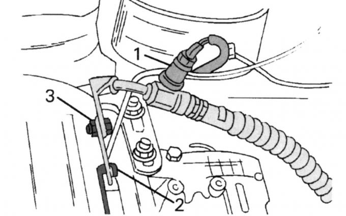
Pic. 55. Location of connections: 1 - membrane switch of the steering mechanism with an amplifier; 2 - wire «masses» in the engine eye; 3 - high pressure hose power steering
- unplug membrane switch 1 (pic. 55) power steering, wire 2 «masses» from the engine lug and high pressure hose 3 of the auxiliary steering pump;
- on a 2-liter engine, unscrew the support bracket for the air conditioner wiring. Remove the heat shield. Release the coolant wiring from the holders, unscrew the two screws and disconnect the coolant hose mount, remove the oil dipstick and unscrew both lower screws;
- on a 1.6- or 1.8-liter engine, remove the heat shield. To do this, unscrew the two screws at the top and two screws at the bottom. Then remove the dipstick;
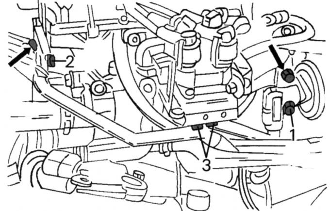
Pic. 56. Elements of the exhaust gas recirculation system (AGR): 1 - valve of the AGR system on the intake manifold; 2 - wiring of the AGR system in the engine eye; 3 - wiring of the AGR system on the ignition coil
- Remove the exhaust gas recirculation system from the cylinder head (AGR). To do this, disconnect the EGR valve 1 (pic. 56) from the intake manifold, EGR wiring 2 from the engine lug and EGR wiring 3 from the ignition coil;
- on a car with a 2-liter engine, disconnect the catalytic converter and the wiring of the Pulse-Air system from the exhaust manifold (three union nuts and four nuts);
- on a car with a 1.6- or 1.8-liter engine, unscrew the catalytic converter from the exhaust manifold (four nuts);
- Disconnect all coolant hoses from the thermostat housing. On a 1.6- or 1.8-liter engine, disconnect the remote thermometer temperature sensor connector;
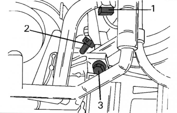
Pic. 57. The position of some multi-pin plugs and the filter of the Pulse-Air system: 1 - coolant temperature sensor plug; 2 - plug of the crankshaft position sensor; 3 - fastening screw
- remove the filter of the Pulse-Air system and disconnect the nearby plugs 1 and 2 (pic. 57);
- put the car jack under the oil pan (with wooden spacer between jack head and motor/drive) and raise the unit in the suspensions to the preload force;
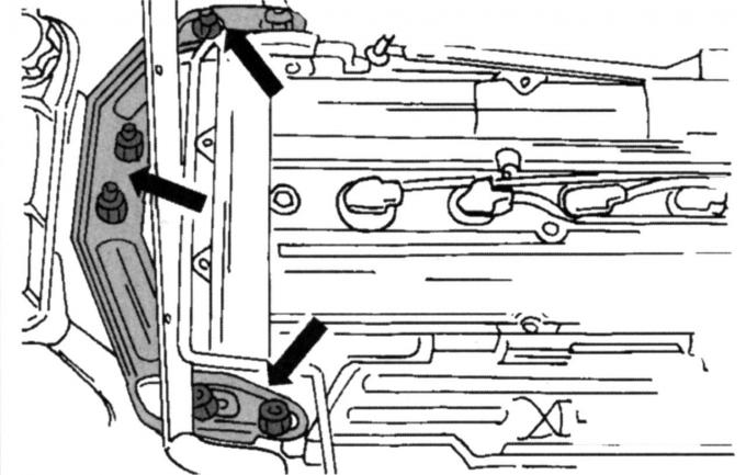
Pic. 32. Attachment points of the right engine mount
- Turn away the right suspension bracket of the engine. On fig. 32 shows how the suspension bracket is strengthened. Always replace self-locking nuts with new ones. After that, remove the bracket;
- on a vehicle with a manual transmission, remove the torque support on the left side. The power unit must be lifted to remove the stop;
- Turn away screws of the console of the auxiliary pump of a steering and take the console;
- Remove the generator suspension brackets;
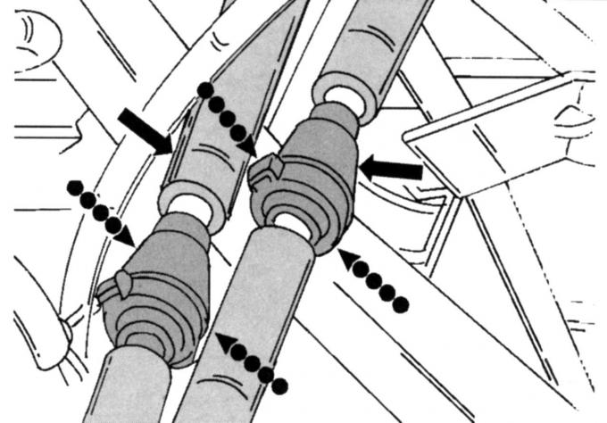
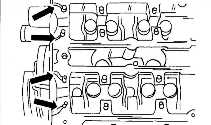
Pic. 58. Disable quick-release constipation
- relieve pressure in the supply system (see subsection «fuel injection system»). Then disconnect the fuel lines. They are fastened with quick-release locks, which are removed as shown in fig. 58 (connections compress and disconnect);
Warning: If fuel is under pressure, gasoline may leak.
- having removed the tension roller of the drive belt, unscrew the middle and upper protective covers of the toothed drive belt;
- Remove the wire ends from the spark plugs. Mark the tips;
- unscrew the cylinder head cover (ten screws) and remove the seal;
- Turn out spark plugs;
Pic. 59. The weakening of the tension of the toothed drive belt: 1 - nut; 2 - tension roller
- loosen the toothed drive belt, to do this, unscrew the nut 1 (pic. 59), install a suitable Allen key. Rotate the belt tensioner in the direction of the arrow and tighten the tensioner to the new position. Remove the toothed drive belt - do not oil or break the toothed drive belt to be reused;
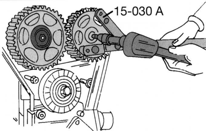
Pic. 45. Camshaft gear holding tool
- Loosen the screws securing both camshaft pulleys, holding them from turning. The clamp shown in fig. 45 is best suited for this purpose. Otherwise, insert a drift into one of the holes and carefully lock it against the cylinder head. Remove both pulleys, marking their belonging;
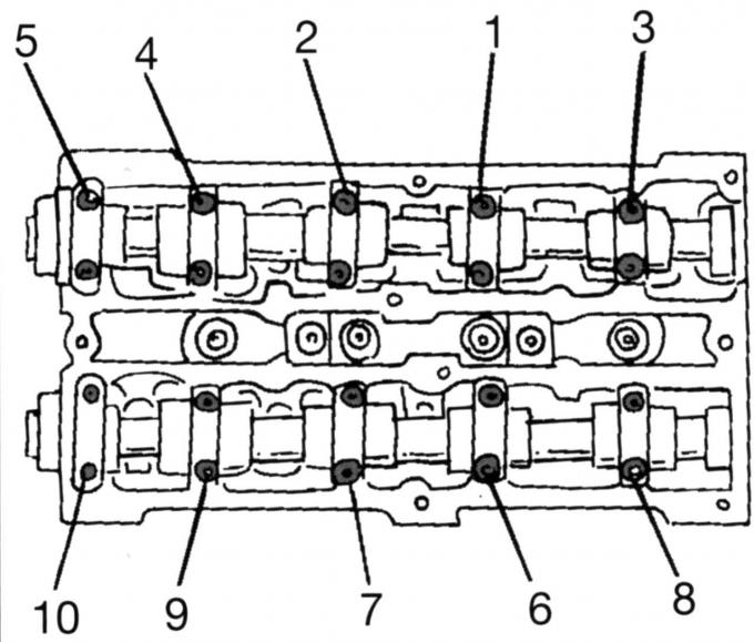
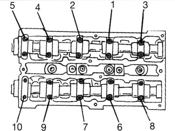
Pic. 46. The sequence of loosening the camshaft bearing caps
- Remove camshafts. To avoid deformation of the shafts, loosen the bearing caps in a certain sequence (see fig. 46). Loosen the nuts of the bearing caps accordingly in the sequence shown by half a turn until the nuts can be loosened by hand. Label the covers and remove them one by one. Carefully remove both camshafts and remove radial sealing rings;
- remove the poppet pushers one by one and set them aside in the sequence required for installation, or mark them;
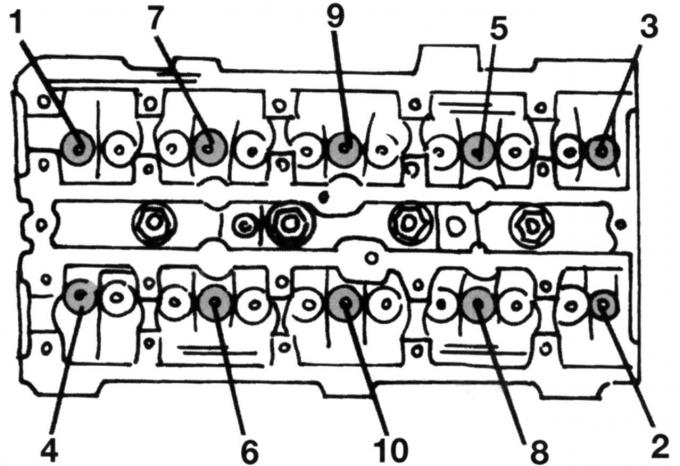
Pic. 60. The sequence of unscrewing the screws securing the cylinder head. Tighten screws in reverse order
- Remove the cylinder head assembly. To do this, unscrew the screws in the indicated in Fig. 60 sequences. After removing the oil dipstick tube, remove the cylinder head (if necessary, help with a rubber mallet) and put it on two wooden blocks;
Note: The cylinder head screws on these engines can only be used twice. Mark them with one or two punch strokes. If the screws already have two notches from a punch, then they have already been used twice.
- if the surface of the cylinder head was ground, the transitions between its surface and the combustion chambers must be processed with sandpaper to eliminate irregularities, but without rounding them off;
- two guide bolts must be machined for installation. On one side of the bolt there should be an M10 thread, on the other side there should be a sawn slot for a screwdriver. Screw in the bolts at two corners of the cylinder head;
Note: When ordering a cylinder head gasket, be sure to specify the engine size as different gaskets are used.
- two fitted bushings are installed in the cylinder block (between the first and second, as well as the third and fourth cylinders). To guide the head when it is installed, the bushings must be well driven into the block. Since the pistons in an unfavorable position of the crankshaft (or camshaft) can hit the valves, turn the crankshaft so that the piston of the first cylinder is about 20 mm below the upper edge of the cylinder bore. The installation order is as follows:
- screw the guide bolts with a screwdriver;
- Install the cylinder head gasket on the block as described above. Both fitted bushings must pass through the corresponding holes in the gasket;
- carefully put on the cylinder head, or lower it with a manual crane onto the block. Make sure that the fitted bushings enter and tap the head with a rubber mallet;
- Screw new screws of fastening of a head of the block of cylinders and tighten them in an order, the return shown on fig. 60. Remember that screws should always be replaced with new ones if they have been used more than once before (see previous note).
Cylinder head screws, i.e. threads or studs must not be lubricated. Tighten the screws with the appropriate wrench in three stages:
- tighten all screws one by one to 25 Nm;
- in the same sequence, tighten the screws to 45 Nm;
- from this position tighten the screws by 105°. Usually a graduated disk is used for this. If you don't have such a disc, you can easily estimate a 105°turn, given that 90°represents a quarter of a full turn;
Warning: The cylinder head screws must be tightened when the engine is cold.
- Install the tube for the oil dipstick and the dipstick itself;
- Establish camshafts. They are marked. The intake valve shaft has an additional cam at the end for the camshaft position sensor. A certain amount of sealant is needed to seal the front camshaft bearing caps in conjunction with the cylinder head;
Pic. 61. Sealing points
- on a head of the block of cylinders grease with sealant the places shown by arrows in fig. 61;
- Lubricate the main journals of the camshafts well with oil and install the shafts in their places;
Pic. 62. Marking of camshaft covers
- Establish covers of bearings of camshafts in order of numbers. Marking is not quite usual as the first cover is marked «0» and is on the output side. Subsequent numbering is shown in fig. 62. All numbers must be visible from the outside;
- screw in all screws of covers and tighten by hand. Then tighten each respective pair of screws in the reverse order of that shown in fig. 46, half a turn, so that all covers are on top of the cylinder head. And again, in the same order, tighten the screws pair by pair with a torque of 10 Nm. Tighten the screws again to 19 Nm. Bearing caps must always remain parallel to the surface of the cylinder head when tightened;
- Hammer or even better tighten new seals with a piece of pipe with a diameter of o-rings. Attach an M10 screw with a large washer to the pipe to tighten the shaft seal. Lubricate the seal lips well;
- Fit the camshaft pulleys. The pulleys must rotate freely on the shafts;
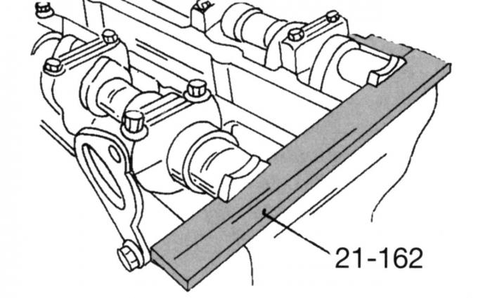
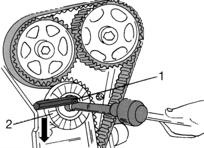
Pic. 63. Caliber for adjusting the valve timing
- set the caliper for adjusting the valve timing, as shown in fig. 63;
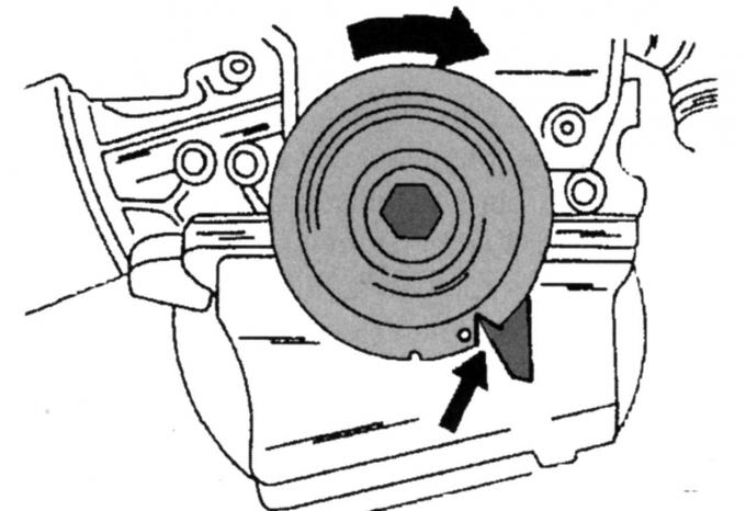
Pic. 64. Setting the crankshaft to top dead center (TDC)
- Turn a cranked shaft so that cut in a pulley has appeared in the position specified in fig. 64. This position corresponds to the TDC of the first cylinder;
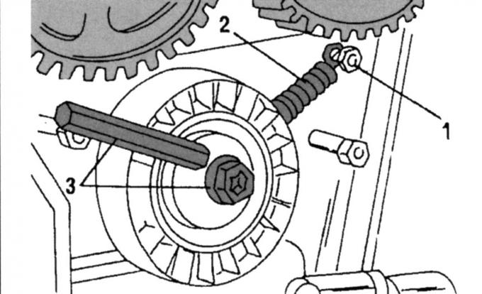
Pic. 65. Pre-installation of the belt tensioner: 1 - support bolt; 2 - spring; 3 - screw
- if spring 2 (pic. 65) the belt tensioner has been removed, it must be reinstalled.
To do this, screw in the safety pin and tighten with a torque of 10 Nm, hang the spring between the pin and the belt tensioner. Insert an Allen key bent at an angle as shown in the illustration and turn. Tighten the tension roller with screw 3 in the new position;
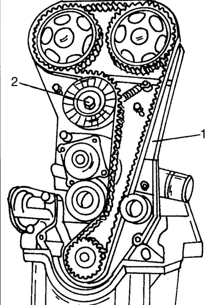
Pic. 66. Placement of the toothed drive belt: 1 - belt, 2 - screw
- Lay the toothed drive belt in a counterclockwise direction on the three pulleys and the belt tensioner. First lay the belt over the crankshaft pulley, keeping the teeth engaged, route the belt around the lower idler pulley and toothed drive belt tensioner on the left, and loop around the left camshaft pulley. Now, keeping the belt firmly in mesh with the teeth of the camshaft pulley, lay it on the right pulley and finally pass it around the inside of the right roller. Make sure that all teeth provide the necessary engagement. Loosen nut 2 (pic. 66), after which the belt tensioner will rush inward to provide the required belt tension;
- lock the camshaft pulleys from turning and tighten both screws to 68 Nm. In this case, the crankshaft must not rotate. After tightening the screws, turn the crankshaft two turns until it is at TDC again;
- tighten the belt tensioner screw to 38 Nm;
- check that the gauge is still aligned according to fig. 63 when the crankshaft is at TDC. Otherwise, loosen the corresponding camshaft pulley and move it slightly. Tighten the screw again to 68 Nm;
- Establish a cover of a head of the block of cylinders on a new sealing lining. Tighten the screws evenly around the circumference, first to 2 Nm and then to 7 Nm;
- screw in the spark plugs (15 Nm) and put on them high-voltage wires according to the order of operation of the cylinders;
- install protective shields. When doing this, pay attention to the fact that the middle cover is correctly located in the bottom cover;
- Install the drive belt pulley and tighten to 48 Nm;
- carry out all other works in the reverse order, taking into account the following tightening torques, Nm:
- generator console 47
- auxiliary pump console
- steering 47
- front engine mount 83
- elements of the recirculation system
- exhaust gases 10
- thermal shield 10
May 1998 release engines.
Remove the head in the following order:
- place the front of the car on supports and unscrew the protective shield under it (nine screws). Unscrew the protective cover over the crankshaft pulley (two screws), if it is set;
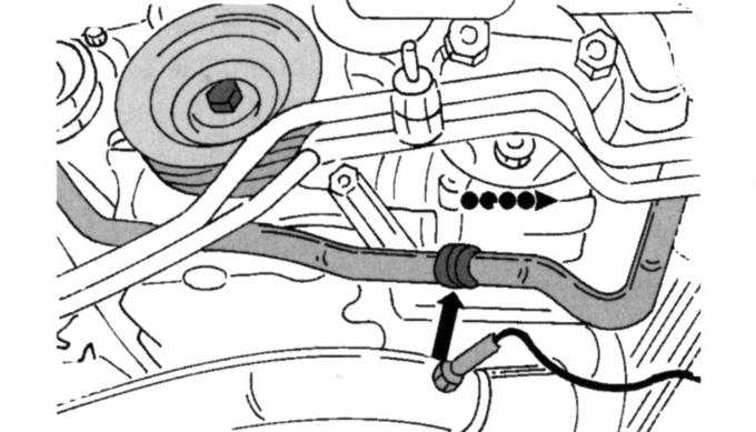
Pic. 67. Disconnecting the coolant hose
- merge a liquid from system of cooling, having disconnected the bottom hose of a cooling liquid in the place specified in fig. 67. The coolant must be collected in a container;
- remove the right forward wheel and facing on the inside of a wheel arch (two screws);
- remove poly V-belt (see separate description);
- unscrew the screw in the middle of the crankshaft pulley and remove the belt pulley (torsional vibration damper). If necessary, press out with two tire mounting levers;
- Turn away the bottom protective casing of a gear drive belt. A screw will be visible to the left and right of the hole;
- Find the plug-in block of the crankshaft position sensor and disconnect it;
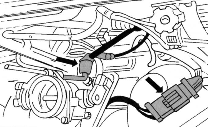
- Disconnect the brake booster low pressure pipe from the intake manifold. The wiring is fastened with a quick-release constipation. Press one side and take out the wiring;
- Remove the plugs from the oil pressure switch. One plug is put on the knock sensor, which is installed next to the oil pressure switch (if it is installed);
- lower the car on wheels;
- Remove an inlet branch pipe. First remove the three screws 1 (see fig. 22) mounts. Remove plug 3 from the sensor and remove hose clamp 4 on the same side. At location 2, unplug the multi-pin connector of the intake air sensor. On the left side is a low pressure hose 5. Remove it;
- Remove the air filter. To do this, disconnect the ventilation hose between the filter and the cylinder head cover. Unhook the rubber ring on the right, remove the air filter from the mount and remove it;
- remove the throttle cable safety clip, disengage the throttle cable at the end of the lever and carefully place the entire cable back (see fig. 54);
- relieve pressure in the supply system (see subsection «fuel injection system»). Then disconnect the fuel lines. They are fastened with quick-release locks, which are removed as shown in fig. 58 (connection is compressed and disconnected);
Warning: If fuel is under pressure, it may leak.
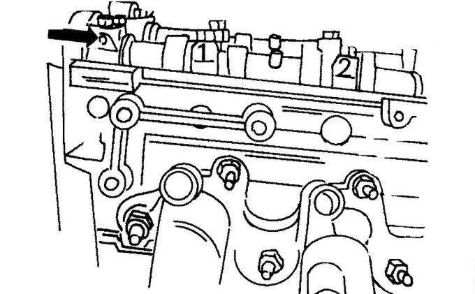
Pic. 68. Low pressure pipe and multi-pin connector
- remove the plug shown in fig. 68, and to the left of it, disconnect the low pressure pipe;
- Remove all low pressure hoses of the exhaust gas recirculation system (AGR) (if it is installed);
- Disconnect all coolant hoses from the thermostat housing;
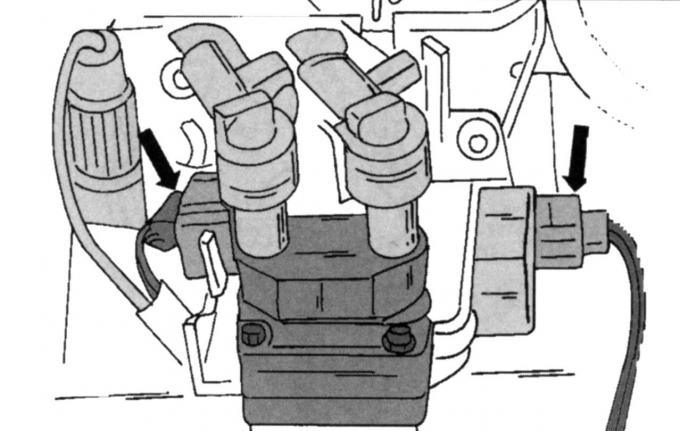
Pic. 69. Ignition coil plugs (left) and noise suppression capacitor (on right)
- remove the plugs from the ignition coil (left arrow, fig. 69) and noise suppression capacitor (right arrow). Remove the plug from the temperature sensor of the remote thermometer;
- unscrew the heat shield;
- Disconnect the connecting pipeline on one of the coolant hoses;
- unscrew the exhaust pipe from the exhaust manifold (four nuts) and disconnect the pipe;
- Remove the guide pipe for the oil dipstick and unscrew the clamp for the wiring of the auxiliary steering pump;
- Remove the expansion tank of the cooling system and set aside. Separate fastening of conducting of a working liquid of a steering. To do this, unscrew the nuts and dowel pins, unscrew the screws in the upper part and set the mount with the pump aside;
- Remove the generator and turn out the top screw of the generator console;
- put the car jack under the oil pan (with wooden spacer between jack head and oil pan) and raise the power unit until the front engine mount is unloaded;
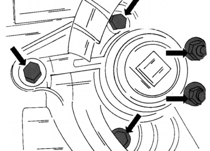
Pic. 70. Attachment points of the front engine mount
- mark the mounting position of the engine mount and unscrew the screws shown in fig. 70. Take out the suspension support;
- unscrew the top protective cover of the toothed drive belt (two screws left and right), but do not remove the cover;
- Remove an average protective cover of a gear drive belt together with a support of a suspension bracket of the engine. Now remove the top shield;
- remove the high voltage wires from the spark plugs one by one (pull the tips up) and unscrew the ten screws securing the cylinder head cover, remove the gasket;
- Turn out spark plugs;
- make sure the piston is at TDC (see fig. 64);
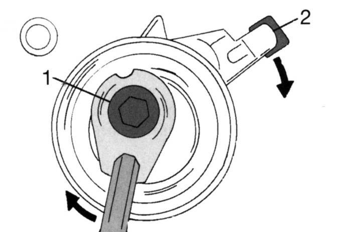
Pic. 71. Loosening the toothed drive belt: 1, 2 - screws
- loosen the toothed drive belt by unscrewing the nut 1 (pic. 71) and inserting a suitable Allen key in the location shown in the illustration. Turn the belt tensioner in the direction of the arrow. Loosen screw 2 four turns and remove the belt tensioner. Remove the toothed drive belt - do not contaminate with oil or break the toothed drive belt that is going to be reused;
- Loosen the screws securing both camshaft pulleys, holding them from turning. The clamp shown in fig. 45 is best suited for this purpose. Otherwise, insert a drift into one of the holes and carefully lock it against the cylinder head. Remove the pulleys, marking their belonging;
- remove the poppet pushers one by one and set them aside in the sequence required for installation, or mark them;
- Remove the cylinder head assembly. To do this, unscrew the screws in the sequence shown in fig. 60, with an interchangeable head wrench, so as not to damage the screw heads;
- remove the cylinder head (if necessary, help with a rubber mallet) and place it on two wooden blocks. The work can be made easier if you have a lifting mechanism at your disposal. In this case, fix the cable or chain in the eyelets, lower the head.
Note: The cylinder head screws on these engines can only be used twice. Mark them with one or two punch strokes. If the screws already have two notches from punching, then they have already been used twice.
- two guide bolts must be machined for installation. The bolts must have an M10 thread 90 mm long on one side, and a sawn slot for a screwdriver on the other side. Install the bolts at the two corners of the cylinder head.
- When ordering a cylinder head gasket, be sure to specify the engine size, as different gaskets are used. Two fitted bushings are installed in the cylinder block (between the first and second cylinders, as well as the third and fourth cylinders), to guide the head during installation, the bushings must be well driven into the block. Since the pistons in an unfavorable position of the crankshaft (or camshaft) can hit the valves, turn the crankshaft so that the piston of the first cylinder is about 20 mm below the upper edge of the cylinder bore.
The procedure for installing the cylinder head is as follows:
- screw the guide bolts with a screwdriver;
- Install the cylinder head gasket on the block as described above. Both bushings must pass through the corresponding holes in the gasket;
- Carefully put on the cylinder head or lower it with a lifting mechanism onto the block. Make sure that the fitted bushings enter, tap the head with a rubber mallet;
- Screw new screws of fastening of a head of the block of cylinders and tighten them in an order, the return shown on fig. 60. Remember that screws should always be replaced with new ones if they have already been used more than once. Cylinder head screws - Threads or rods must not be lubricated. The screws are tightened with the appropriate wrench in three stages:
- tighten all screws one by one to 15 Nm;
- tighten all screws in the same sequence to 40 Nm;
- from this position tighten the screws by 90° (quarter turn). No further tightening required;
Warning: The cylinder head bolts must be tightened when the engine is cold.
- Establish camshafts. They are marked. The intake valve shaft has an additional cam at the end for the camshaft position sensor. A sealant is required to seal the connection between the front camshaft bearing caps and the cylinder head;
- lubricate with sealant the places shown by arrows in fig. 61, on the cylinder head;
- Lubricate the main journals of the camshafts well with oil and install the shafts in their original places;
- Establish covers of bearings of camshafts according to their numbers. Marking is not quite usual, as the first cover is marked «0» and is on the output side. Subsequent numbering is carried out as shown in Fig. 62. All numbers must be visible from the outside;
Pic. 71a. Camshaft bearing cap loosening sequence
- screw in all screws of covers and tighten by hand. Then tighten each respective pair of screws half a turn in the reverse order shown in fig. 71a. Again, in the same order, tighten the screws, pair by pair, to a torque of 10 Nm. Tighten all screws again to 19 Nm. Bearing caps must always remain parallel to the surface of the cylinder head when tightened;
- drive in or, even better, tighten new oil seals with a piece of pipe with a diameter of o-rings. Screw an M10 screw with a large washer to the pipe to tighten the shaft seal. Lubricate the seal lips well with oil;
- Fit the camshaft pulleys. The pulleys must rotate freely on the shafts;
- set the caliper for adjusting the valve timing, as shown in fig. 63;
- Turn a cranked shaft so that cut in a pulley has appeared in the position specified in fig. 64. This position corresponds to the TDC of the first cylinder;
- Lay and tighten the toothed drive belt as described in the relevant subsection. It should be noted that the design of the toothed belt drive has been changed since about February 1999. In the old design, the guide roller is used for the toothed belt drive at the bottom;
- lock the camshaft pulleys from turning and tighten both screws to 68 Nm. In this case, the crankshaft must not rotate;
- remove the inserted tools and turn the crankshaft two turns until it is again at TDC. Check the timing again as described when replacing the toothed drive belt. If everything is in order, i.e. the gauge is still level, as shown in fig. 63, with the crankshaft position corresponding to TDC, remove the tools. Otherwise release the corresponding camshaft pulley and move it a little. Tighten the screw again to 68 Nm;
- Establish a cover of a head of the block of cylinders with a new sealing lining. Tighten the screws evenly around the circumference, first to 2 Nm and then to 7 Nm;
- screw in the spark plugs (15 Nm) and put on high-voltage wires according to the order of operation of the cylinders;
- Approximately install the upper protective cover of the toothed drive belt and install the middle protective cover with the engine mount. Tighten the screws to 50 Nm. After that, you can attach the top cover (10 Nm);
- Install the front engine mount and tighten to 83 Nm. After that, lower the engine again and remove the jack;
- Install the V-ribbed belt as described below;
- carry out all other work in the reverse order, taking into account the following tightening torques Nm:
- generator 25
- lower protective cover of the toothed belt 10
- crankshaft pulley 115
Visitor comments