A cylinder head gasket defect is identified by one or more of the following symptoms:
- Loss of power.
- Loss of coolant White exhaust gases when the engine is warm.
- Oil loss.
- The presence of coolant in the engine oil, the oil level does not decrease. however, it is getting smaller. Gray color of engine oil, foamy emulsion on the oil level indicator, liquid oil.
- Engine oil in coolant.
- The coolant boils a lot.
- There is no compression in two adjacent cylinders.
Withdrawal
Disconnect ground wire (-) battery.
Caution: Disconnecting the battery will erase the contents of the electronic memories, such as engine trouble codes or radio codes. Before switching off, also read the instructions in chapter "Removing and installing the battery".
Remove the air filter together with the suction hose, see p. 59.
Drain the coolant see p. 38.
Take off the throttle.
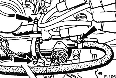
Release clamps -arrows- and disconnect coolant hoses from thermostat housing: to expansion tank, coolant connecting hose for cylinder head.
Depending on the engine: Disconnect the second heating hose at the cylinder head, at the intake manifold or at the cover of the automatic fuel mixture enrichment device at start-up. Loosen the clamp first.
Detach the breather hose at the cylinder head cover.
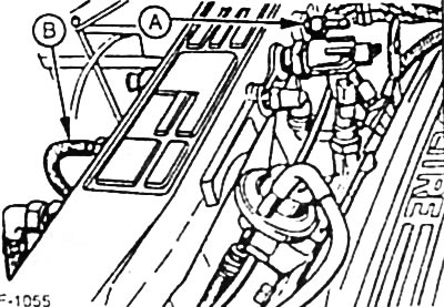
4-cylinder injection engine: Detach vacuum hoses from MAP sensor -A- and activated charcoal container -B-. To facilitate subsequent assembly, pre-mark the hoses with adhesive tape.
Carburetor engine: Disconnect the vacuum hose from the control unit.
If equipped, disconnect vacuum hoses from A/C compressor and automatic transmission. To facilitate subsequent assembly, pre-mark the hoses with adhesive tape.
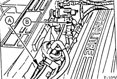
Injection engine: Loosen clamps and disconnect fuel hoses from pressure accumulator -A- and fuel lines -B-. Before disconnecting, cover the connectors with rags to prevent fuel splashing. Plug the fuel lines quickly with suitable plugs. To do this, insert, for example, clean threaded bolts of the appropriate diameter into the hoses. To facilitate subsequent assembly, pre-mark the hoses with adhesive tape.
Attention: Carefully disconnect the fuel hoses so that the pressure in the fuel system can be relieved.
Release the clamps on the carburetor engine and disconnect the fuel hoses from the carburetor and from the fuel pump.
Disconnect the plug-in connectors or unscrew the fastening of all electric cables going to the engine. To facilitate subsequent assembly, pre-mark the wires with adhesive tape.
- Combination plug connector for fan motor.
- Plug connector for speed/crankshaft position sensor (CPS)
- Injection engine Oxygen sensor connector
- Injection engine: Combination plug connector for engine management wiring harness
- Injection engine, combi-plug for valve injectors
- Carburetor engine: plug connector for automatic start-up enrichment device
- Carburetor engine, intake manifold heater connector
- Carburetor Motor: Carburetor Stepper Motor Combination Plug Connector
- High voltage wire, terminal 4 at the ignition coil.
Raise the car on the goats.
If equipped, remove the lower engine compartment cover.
Unbolt the front exhaust pipe to the exhaust manifold, see p. 80.
Lower the car.
Remove toothed belt see p. 13.
Remove the tips of the spark plugs and unscrew the fastening of the cover of the ignition distributor.
Remove spark plugs.
Loosen the cylinder head cover bolts.
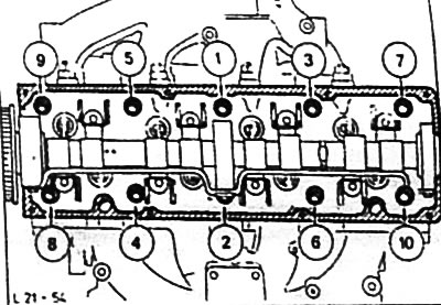
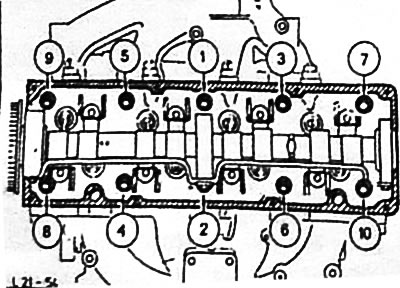
ONS engine: release all cylinder head mounting bolts in reverse numbering sequence, i.e. from 10 to 1, first by 1/2 turn, then unscrew the bolts completely.
Caution: Loosening the bolts in the wrong sequence can warp or crack the cylinder head.
Check that all hoses and wires from the cylinder head to the engine and body are disconnected.
With the help of an assistant, remove the cylinder head from the engine.
Caution: Do not place the removed cylinder head directly on the sealing surface, as fully open valves may be damaged. Place the cylinder head on 2 wooden blocks
Installation
Clean the sealing surface of the crankcase from seal residues with a suitable scraper. Never scratch the sealing surfaces. When doing this, make sure that dirt does not get into the bores of the cylinder block. Cover holes with rags.
Check the cylinder head for cracks and the cylinder sliding surfaces for notches.
Check the cylinder head bolt holes for oil or other fluid. If compressed air is not available to blow through the holes, use a small screwdriver to inject a clean shake into the holes to soak up the liquid.
Attention: The liquid from the holes must be removed in any case.
The cylinder head gasket must be replaced.
To center the cylinder head, make your own guide pins. To do this, cut off the heads of two old bolts for fastening the cylinder head and saw through the groove for a screwdriver in each of the rods.
Screw guide pins into holes 7 and 9 (see drawing L21-54).
Lay the new cylinder head gasket without sealant on the guide pins so that it does not block any holes.
Install the cylinder head.
Unscrew the guide pins with a screwdriver.
New mounting bolts in the area of their heads and threads are easy to lubricate and tighten by hand until they stop.
Caution: The cylinder head bolts must be replaced.
Tighten cylinder head bolts in 3 steps.
In each step, the bolts are tightened in sequence from 1 to 10.
- Reception 1: using a torque wrench with a torque of 40 Nm.
- Reception 2: using a torque wrench with a torque of 75 Nm.
- Technique 3: after a 5-minute pause, use the locked torque wrench to tighten by 90°.
Attention: The cylinder head bolts are not tightened after a certain mileage. Tighten very carefully. The torque wrench must be checked for accuracy before tightening. To facilitate tightening operations at a certain angle, a special protractor, for example, HAZET 6690, is required. cylinder head.
Fit the cylinder head cover with a new gasket. Using a torque wrench, tighten the cover bolts in 4 steps to the prescribed torque.
- Reception 1: bolts 1 to 6 torque 6 Nm.
- Reception 2: bolts 9 and 10 with a torque of 2 Nm.
- Reception 3: bolts 7 and 8 with a torque of 6 Nm.
- Reception 4: bolts 9 and 10 with a torque of 6 Nm.
Screw in spark plugs and tighten to 20 Nm.
Screw on the distributor cap and put on the spark plug tips in accordance with the firing order of the cylinders (1-3-4-2).
Raise the car on the goats.
Install the front exhaust pipe see p. 80.
If equipped, install the lower engine compartment cover.
Lower the car.
Connect in accordance with the designations applied before removal and fix the vacuum hoses and electrical wires.
Install throttle.
Connect and secure the coolant hoses with clamps.
Connect in accordance with the designations applied before removal and secure the supply and return fuel hoses with clamps.
Connect the crankcase ventilation hose to the cylinder head.
Install the air filter together with the suction hose, see p. 59.
Check engine oil level, top up if necessary. If the cylinder head gasket is damaged, replace the engine oil and oil filter as There may be coolant in the engine oil.
Check the concentration of antifreeze in the coolant and fill in the coolant, see p. 38.
Connect ground wire (-) battery.
If available, set the clock and enter the anti-theft code for the radio.
Check and, if necessary, adjust the ignition timing, see p. 50.
Check and, if necessary, adjust the engine idle speed see p. 64.
Warm up the engine to normal operating temperature, check the levels of working fluids and check the connections of all hoses for tightness.
Visitor comments