Caution: Operating procedures and instructions applicable to all engines are described in the above chapter by engine ONS. This chapter only presents the significant differences.
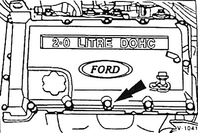
All figures are for a 2.0L DOHC engine.
Disconnect the fuel lines by pressing the strips.
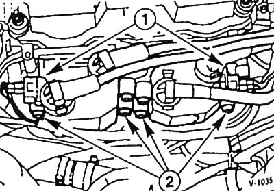
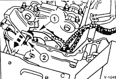
Remove the ignition coils. To do this, disconnect the 2 plug connectors "1", unscrew the 6 bolts "2" and pull the high-voltage wires out of the plug cover.
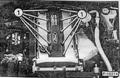
16V engine: unscrew the ignition coil cover fastener "1". The two ignition coils are located above the second and fourth cylinders, respectively. Remove the spark plug tips, unscrew the 2 fastening bolts for each coil and remove the coils.
Unscrew the guide tube for the engine oil level indicator and pull it out with an upward movement.
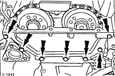
Remove 11 bolts and 4 nuts securing the cylinder head cover.
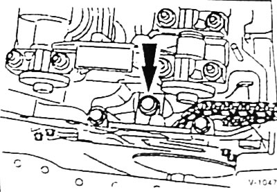
Unscrew the fastening of the upper chain drive cover.
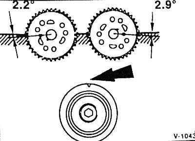
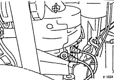
Turn the crankshaft to the position where the piston of cylinder 1 is at TDC of the combustion process, see the figure. Turning the crankshaft is described on p. 13.
Loosen the upper chain drive guide fastener.
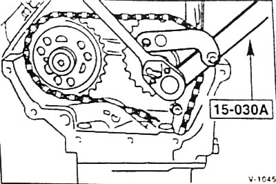
Remove the bolts securing the camshaft sprockets. Hold the sprockets using the FORD 15-030A tool.
Using a waterproof marker or felt-tip pen, draw a line through each sprocket and drive chain to mark the position of the chain relative to the sprockets for reassembly.
Remove the camshaft sprockets. Make sure that the drive chain does not fall into the chain drive shaft. Use a wire to hang the drive chain to the side so that it does not interfere with further dismantling.
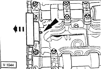
Using pliers, remove retaining ring "1" from support pin "2".
Caution: The retaining ring must not fall into the chain drive shaft. Place a clean cloth underneath!
Screw the M6 bolt into the support pin "2" and unscrew the pin.
Remove the chain tensioner lever from the chain drive shaft.
Remove the hydraulic chain tensioner tappet from the cylinder head and discard.
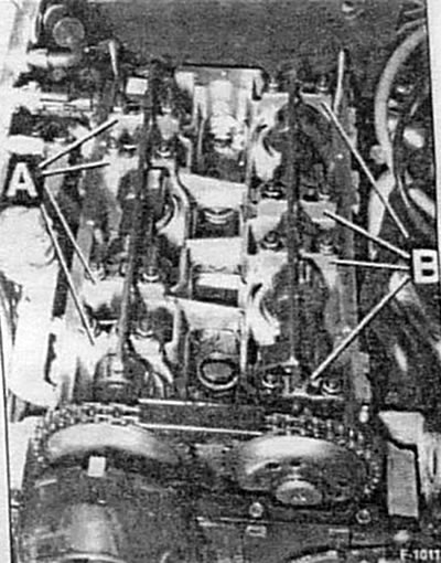
Loosen the fastener evenly and remove the bearing caps "A" of the intake camshaft and the bearing caps "B" of the exhaust camshaft.
Caution: The camshaft bearing caps are marked, for example, L3, and must not be interchanged or replaced.
Remove the camshafts.
Remove the hydraulic valve lifters.
Caution: Before loosening the bolts, make sure that the cylinder head has cooled to at least +30°C.
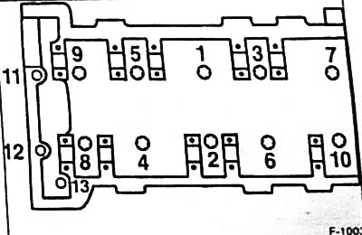
First, unscrew the additional bolts 11, 12 and 13 with internal slots in the head.
After this, loosen the bolts with internal slots in the head in sequence from 10 to 1 by about 1/2 turn in the first step, by one full turn in the second step, and unscrew the bolts completely in the third step.
Installation
Note: To ensure flatness, the cylinder head may be reworked by no more than 0.3 mm. The height of the machined head must not be less than 147.45 mm, and the height of the combustion chamber must not be less than 13.8 mm.
Place the new cylinder head gasket without sealant on the guide bushings so that it does not cover any openings.
Caution: To avoid damage to pistons and valves, before installing the cylinder head, turn the crankshaft so that the piston of cylinder 1 is approximately 25 mm below TDC. After the cylinder head and camshafts have been installed and the camshafts have been set to TDC, turn the crankshaft again to the position in which the piston of cylinder 1 is at TDC.
Attach the cylinder head.
New mounting bolts in the head and thread area are easy to lubricate and tighten by hand until tight.
Note: The cylinder head mounting bolts must be replaced. Insert the M11 bolts into holes 1 through 10, insert two long M8 bolts into holes 11 and 12, and insert the short M8 bolt into hole 13.
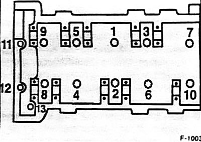
Tighten the M11 cylinder head mounting bolts in 4 stages. In each stage, tighten the bolts in sequence from 1 to 10.
- Method 1: using a torque wrench with a torque of 40 Nm.
- Method 2: using a torque wrench with a torque of 55 Nm.
- Step 3: Using a locked torque wrench, tighten by 90°.
- Step 4: Using a locked torque wrench, tighten the screw 90° further.
Attention: The cylinder head mounting bolts are not tightened after a certain mileage.
Tighten new M8 bolts -11/12/13- on the end of the cylinder head to a torque of 40 Nm.
Note: At the service station, the camshafts can be checked for runout if necessary.
The camshafts and their bearings are easily lubricated with engine oil.
Based on the position of the crankshaft belt pulley, check whether the piston of cylinder 1 is approximately 25 mm from TDC.
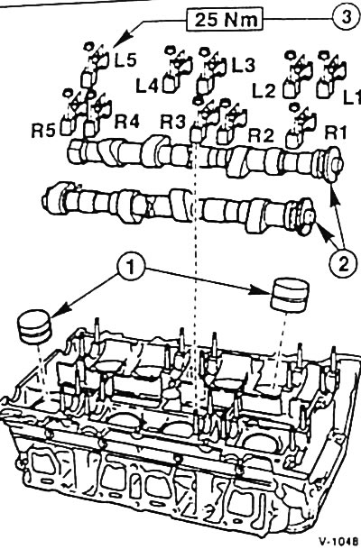
Valve lifters "1" are easy to lubricate and install in their original places, in which they were before removal.
Place camshafts "2" in a position approximately corresponding to the TDC of the piston of cylinder 1, so that the receiving grooves on the side where the sprockets are installed are located outward.
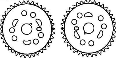
Caution: Do not damage the working surfaces of the bearings. R - intake side, L - exhaust side. The intake camshaft is identified by two identification rings located between the fourth and fifth cams.
Place the bearing caps "3" of the camshafts in accordance with the markings on them and tighten the caps evenly to a torque of 25 Nm. At the same time, tighten the fastening of the upper chain drive guide.
Caution: After tightening the camshaft bearing caps and installing the drive chain, the crankshaft may not be turned earlier than 15 minutes later. During this time, the hydraulic tappets settle. If this time is not maintained, the valves and/or pistons may be damaged.
If a used camshaft is installed, it is necessary to measure the axial clearance. At the service station, a linear movement indicator is used for this, which is attached to the cylinder head. Press the camshaft towards the chain drive and set the indicator scale to "0". Then press the camshaft in the opposite direction and read the reading on the indicator scale. The prescribed value is 0.02-0.26 mm.
Place the camshafts and crankshaft in the position corresponding to TDC for piston of cylinder 1.
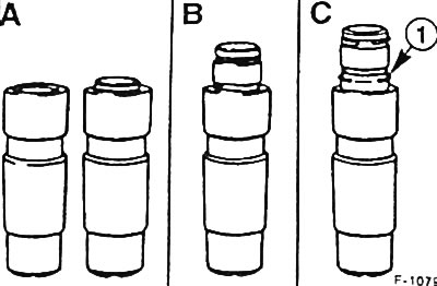
Caution: Only a new, locked hydraulic tappet "A" must be installed. A partially or completely unlocked hydraulic tappet -B/C- must be disposed of.
Carefully install the fixed hydraulic tappet into the cylinder head with the piston facing up.
Caution: Risk of injury!
Insert the chain tensioner lever.
Insert the support pin into the hole and secure with the retaining ring.
Caution: The retaining ring must not fall into the chain drive shaft. Place a clean cloth underneath!
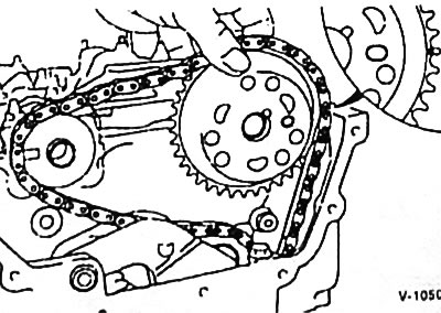
Place the drive chain on the exhaust camshaft sprocket so that the marks made before removal match. The copper links must cover the mark on the sprocket. At the same time, the pull (long) side of the chain must be tightly tensioned, and the camshaft sprocket must be in the position corresponding to TDC for the piston of cylinder 1 (see Figure V-1043). Tighten the sprocket fastening to the camshaft firmly by hand; if necessary, turn the camshaft by the untreated side with pliers so that the sprocket is fixed on the camshaft.
The drive chain and intake camshaft sprocket are installed in the same manner.
Note: The drive chain between the camshaft sprockets should have a slight slack.
Turn the crankshaft clockwise until the intake camshaft begins to turn.
For a hydraulic tappet with a protruding piston (in the figure F-1079 this is the 2nd piston from the left), release the piston by pressing the tension lever down with your hand.
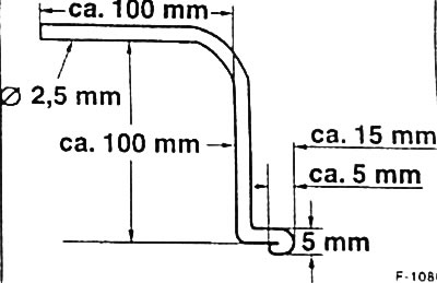
For a hydraulic pusher without a protruding piston (in Figure F-1079, this is the 1st piston on the left), unfasten the piston using a device made independently from a welding electrode with a diameter of 2.5 mm in accordance with Figure F-1080.
Using a screwdriver, carefully lift the chain tensioner lever and insert the device between the chain tensioner lever and the piston. Remove the screwdriver and, by pressing the tensioner lever down with your hand, release the piston. Remove the device.
Holding the camshaft sprockets with a special FORD 15-030A tool, tighten them to a torque of 60 Nm.
Turn the engine crankshaft in the direction of its rotation by one revolution. The marks on the camshaft sprockets should be facing each other at the level of the upper edge of the cylinder head.
Turn the engine crankshaft in the direction of its rotation one more revolution and check whether the piston of cylinder 1 is at TDC (see Figure V-1043). If the adjustment is incorrect, the hydraulic tappet must be removed and reinstalled again.
Attach the new plastic chain guide to the holder.
Place the upper timing chain cover with a new sealing gasket and tighten the cover fastening to a torque of 10 Nm. In doing so, align the upper edge of the cover with the sealing surface of the cylinder head. Maximum downward displacement: 0.13 mm.
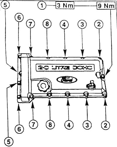
Attach the cylinder head cover with a new sealing gasket and tighten the 11 bolts and 4 nuts securing the cover in the specified sequence, first to a torque of 3 Nm, and then to a torque of 9 Nm.
Tighten the oil level indicator guide tube to a torque of 20 Nm.
Tighten the ignition coil fastenings to a torque of 10 Nm.
(The text of the article was copied from the website fordbook)