Contents: Removal ↳ Installation ↳
Removal
1. Remove the intake manifold (section 8).
2. Remove the exhaust manifold (section 9).
3. According to the recommendations in section 3 remove the valve cover.
4. Drain the cooling system. Disconnect the radiator hose from the thermostat housing on the left side of the engine. Disconnect the temperature sensor wire, unscrew the nut securing the negative wire to the thermostat housing and pull out the wire of the electric fan temperature switch (located in the cylinder head directly under the thermostat housing) (see chapter 3).
5. Unscrew the bolt securing the ignition coil to the head, loosen the bolt securing the bracket to the block and turn the bracket forward (see chapter 5).
6. Remove the distributor cap and wires (see chapter 5).
7. Remove the drive belt (chapter 1).
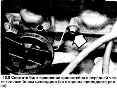
8. Unscrew the engine oil dipstick tube bracket bolt (see figure).
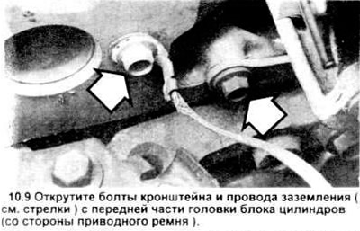
9. Unscrew the bracket bolts from the front end of the cylinder head (end of the drive belt) (see figure).
10. Remove the valve levers and push rods (section 4).
11. Loosen the head bolts, adding 1/4 turn at a time until they can be turned by hand. Go from bolt to bolt in the reverse order of tightening, as shown in Figure 10.17. Remember that the rear bolts are longer than the front ones - they must all be installed strictly in their places.
12. Separate the head from the block. If it is stuck, carefully pry the front part of it off using the engine mount as a support point (see picture).
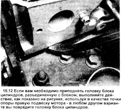
Caution: Do not try to move the head anywhere else with the lever, you will damage it.
Installation
13. The contact surfaces of the cylinder head and block must be perfectly clean before installing the head. Use a scraper to clean off all carbon deposits and scrape off the remainder of the old gasket, then clean the contact surfaces with lacquer thinner or acetone.
If oil remains on the surfaces when installing the head, the gasket will not fit tightly and there will be leaks. When working with the block, stuff the cylinders with a special clean rag to avoid dust and dirt getting in. Use a vacuum cleaner to get rid of any debris and dirt that gets into the cylinder.
14. Check the contact surfaces of the block and head for deep scratches, dents and other damage. If the damage is minor, it can be removed with a file; if it is serious enough, mechanical treatment is required.
15. Using a tap of the appropriate size, tap the threaded holes for the bolts. Mount each bolt in a vice and run a die along the threads to remove corrosion and restore the threads. Dirty, corroded, or damaged threads will distort the torque readings when tightening.
16. Since there are no alignment pins on the head, make sure the gasket is aligned after installing the head.
17. Lower the cylinder head onto the block. Install the cylinder head bolts into their sockets and tighten with your fingers. Tighten the bolts in two steps to the specified torque value, following the order shown (see figure).
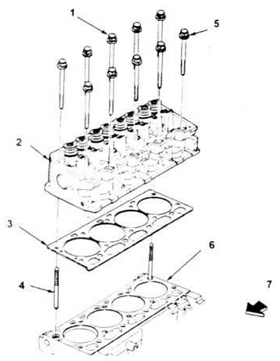
10.17, a. Cylinder head installation procedure.
1. 5 bolts M11x1.5x100.
2. Cylinder head assembly.
3. Gasket.
4. 2 guide bolts.
5. 5 bolts M11x1.5x80.0.
6. Cylinder block.
7. Front of the engine.
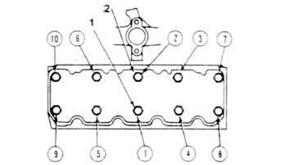
10.17, b. Cylinder head bolt tightening sequence - remember that the front bolts are shorter than the rear ones.
1. 5 bolts M11x1.5x100.
2. 5 bolts M11x1.5x80.0.
18. Installation is carried out in the reverse order of disassembly.
[A copy of the article is available on the website: fordbook]