Contents: Examination ↳ Ignition coil primary circuit… ↳ Ignition coil secondary circuit… ↳ Electrical conductivity of the… ↳ Wiring ↳ Primary Ignition Coil Voltage ↳ Supply voltage of ignition coil ↳ Replacing the ignition coil ↳
Examination
Ignition Coil Primary Circuit
1. Disconnect the electrical connector from the ignition unit. Check for corrosion and damage, then reconnect.
2. Install a 12-volt light bulb in the circuit between the TACH coil terminal and engine ground (see illustration).
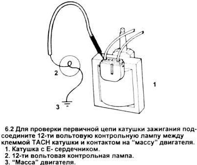
3. Crank the engine.
4. If a flashing light appears or if the light is dim, see paragraph 7.
5. If the light goes out or is too dim, see paragraph 16.
6. Remove the test light.
Ignition coil primary circuit resistance
7. Turn the ignition key to the off position.
8. Disconnect the ignition coil electrical connector and check it for possible contamination, corrosion, or damage.
9. Measure the resistance between the primary terminals of the coil (see figure).
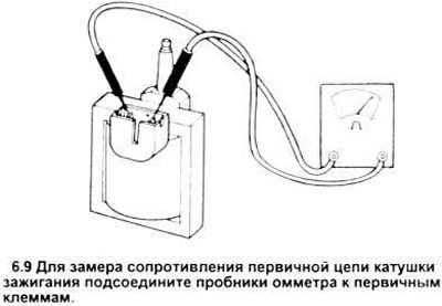
10. If the obtained resistance is within the specification limits, proceed to paragraph 12.
11. If the resistance obtained is less than or greater than the specification, replace the ignition coil (paragraphs 49 through 52).
Ignition coil secondary circuit resistance
12. Measure the resistance between the negative primary terminal and the secondary terminal of the ignition coil (see figure).
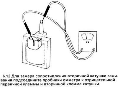
13. If the obtained resistance value corresponds to that specified in the specification, proceed to paragraph 25.
14. If the resistance value obtained is less than or greater than the specification, replace the coil (paragraphs 49 through 52).
15. Reconnect the wires to the ignition coil.
Electrical conductivity of the primary circuit of the coil
16. Disconnect the electrical connector from the ignition module. It may be dirty or damaged.
17. Connect the negative lead of the voltmeter to the base of the distributor.
18. Measure the battery voltage and remember the obtained value.
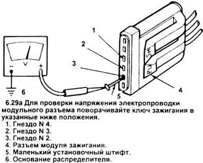
19. Connect the positive lead of the voltmeter to the small pin (nail) inserted into the electrical connector block 2 (see figure).
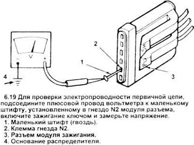
Be careful not to short the pin to ground.
20. Turn the ignition key to the "on" position and measure the voltage at electrical connector 2.
21. If the measured voltage is 90% of the battery voltage, proceed to checking the wiring system (paragraph 25).
22. If the measured voltage is less than 90% of the battery voltage, proceed to paragraph 35.
23. Turn off the ignition.
24. Pull the pin out of the electrical connector.
Wiring
25. Disconnect the electrical connector from the ignition module. Check it for dirt, cracks, corrosion, or damage.
26. Disconnect the wire from terminal S of the starter relay.
27. Connect the negative lead of the voltmeter to the base of the distributor.
28. Measure the battery voltage and remember its value.
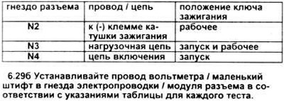
29. Using a workbench, measure the voltage at the terminals of the electrical connector by connecting the positive lead of the voltmeter to a small pin inserted into one of the sockets of the connector for each measurement; in this case, the ignition key must be in the indicated position (see figures).
30. If the measured voltage in all three sockets is 90% of the battery voltage, refer to the EEC - IV/TFI - IV system check in section 10.
31. If the measured voltage is less than 90% of the battery voltage, check the wiring and connectors (see the wiring diagrams at the end of the book for the relevant circuits). Check the ignition key - possible damage and wear (see chapter 12).
32. Turn off the ignition.
33. Pull the pin out of the connector socket.
34. Connect the wire to the S terminal of the starter relay.
Primary Ignition Coil Voltage
35. Connect the negative lead of the voltmeter to the base of the distributor.
36. Measure and remember the battery voltage.
37. Turn the ignition key to the "on" position.
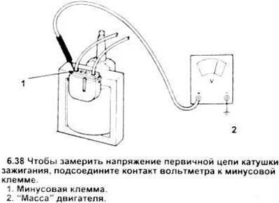
38. Measure the voltage at the negative terminal of the ignition coil (see figure).
39. If the reading obtained is 90% of battery voltage, check the wiring between the ignition module and the negative terminal of the coil.
40. If the value is less than 90% of the battery voltage, then, after checking the wiring between the module and the coil, proceed to paragraph 42.
41. Turn off the ignition.
Supply voltage of ignition coil
42. Disconnect the ignition coil wiring.
43. Connect the negative lead of the voltmeter to the base of the distributor.
44. Measure the battery voltage.
45. Turn on the ignition.
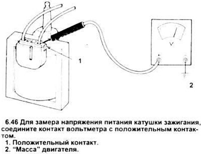
46. Measure the voltage at the positive terminal of the ignition coil (see figure).
47. If the measured voltage is 90% of the battery voltage, check the connector and terminals of the coil - there may be dirt, damage or corrosion.
If the connector and terminals are clean, replace the ignition coil itself (paragraphs 49 through 52).
48. If the voltage reading is less than 90% of the battery voltage, check and repair the circuit between the coil and the ignition switch (see wiring diagrams at the end of the book). Check the ignition switch for damage and wear (see chapter 12).
Replacing the ignition coil
49. Disconnect the cable from the negative battery terminal.
50. Disconnect the high-voltage wire from the coil, then disconnect the primary electrical connector from the coil (see figures).
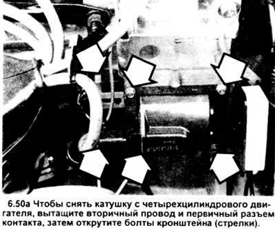
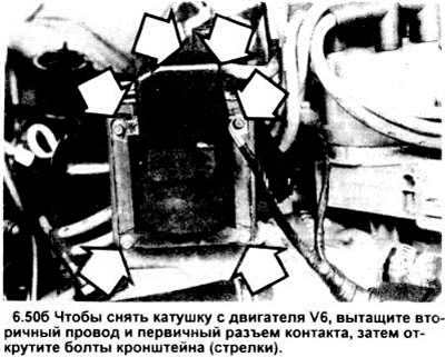
51. Unscrew the bracket bolts and disconnect the coil.
52. Installation is carried out in reverse order.