Contents: Examination ↳ Replacement ↳
Caution: The electronic ignition unit is very fragile. The following tests can only be carried out on the correct equipment by a person who knows how to handle it. If the operations are not carried out carefully, step by step, it is easy to damage the electronic unit / and / or other electronic devices, including the EEC - IV microprocessor itself
Examination
EEC - IV / TFI - IV
1. Remove the electrical connector from the ignition unit. Check for dirt, corrosion and/or damage, then re-insert.
2. Pull out the connector located directly above the ignition unit connector (see section 8).
3. Check for sparking using a calibrated spark tester (see section 6).
4. If there is no spark, proceed to checking the TFI module - IV distributor (paragraph 7).
5. If there is spark, the cause is either the Integrated Mileage/Aging Sensor (IMS) or the Electronic Control Module (ECM) inside the EEC - IV.
6. Remove the spark tester and disconnect the single connector. TFI Distributor Block - IV.
Note: A new ignition module must be purchased before beginning this test.
7. If the module is mounted on a distributor, the distributor must be removed (see section 8). Connect the distributor and the engine with a temporary contact.
8. Install the new unit (see below) Connect the housing harness to the TFI - IV If the unit is mounted on the distributor, make sure the entire assembly is grounded. Rotate the distributor shaft by hand (distributor mounted unit) or crank the engine (hood mounted unit) and check for sparking at the coil wire with a spark tester (see section 6).
9. If there is a spark, then the old module is faulty. Leave the new module in place, install the distributor if it was removed (see section 8).
10. If there is no spark, then the sensor is damaged. Your old unit is OK, and you need to overhaul or install a new distributor.
Replacement
Block mounted on the distributor (all models except late versions 3.8LV6).
11. Remove the distributor from the engine (see section 8).
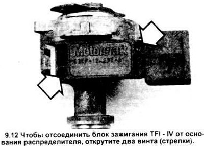
12. Remove the two block mounting screws by inserting a 7/32-inch deep socket head 1/4 inch deep (see illustration).
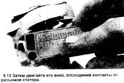
13. Pull the block down to disconnect its contacts from the stator contacts (see figure).
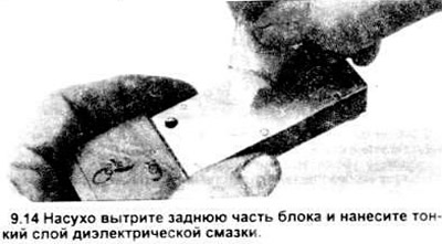
14. When installing an old or new unit, clean its rear surface and apply a thin layer of silicone dielectric grease to it (see figure).
15. Assembly is carried out in reverse order.
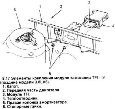
Hood mounted block (late 3.8LV6 engines).
16. Unscrew the screws securing the filter screen to the top of the hood.
17. In the engine compartment, separate the hood seal from the filter screen and the hood panel near the block assembly (see figure).
18. Lift and remove the filter screen to gain access to the unit assembly.
19. Disconnect the electrical connector from the module assembly.
20. Unscrew the two nuts and remove the block assembly and heat sink.
21. Unscrew the screws and separate the block from the heat sink.
22. Installation is carried out in the reverse order. Before installing the block in the heat sink, apply silicone dielectric grease to the metal rear surface of the block (see paragraph 14). When installing the heat sink and the block, make sure that the fins of the heat sink are directed downwards.
The original text is provided on an online resource (www.fordbook.ru)