Note: Before diagnosing the starter, make sure the battery is fully charged.
General check
1. If the starter motor does not turn at all when the ignition is on, check whether the gear shift lever is in "neutral" or "parking" (for an automatic transmission), and whether the clutch pedal is pressed (manual transmission).
2 Make sure the battery is charged and that all wires on the battery terminals and the starter relay are in good condition.
3 If the starter motor rotates, but the car engine does not turn over, then the starter is faulty and will have to be replaced (see section 19).
4. If, when you turn the key, the starter motor does not work with the relay working (clicks are heard), then the problem is either in the battery to which the relay contacts are connected, or in the contacts of the starter motor itself.
5. If the clicks are not heard when turning the ignition key, then either the starter relay circuit is open or the relay itself is faulty.
Check the starter relay circuit (see wiring diagrams at the end of the book), or replace the relay (see section 20).
6. To test the starter relay circuit, remove the connector from the relay wire (red with blue stripe). Make sure the wire connections are clean and tight and the relay bracket is engaged.
If the contacts are OK, check the relay operation using a connecting wire. To do this, put the gearbox in "park" (automatic), and the manual in neutral. Remove the removable tip from the relay. Connect one end of the connecting wire to the positive contact of the battery, and the other to the relay contact. If the starter now works, then the relay is OK. The problem is in the ignition key, the neutral position sensor, or the ignition circuit wires.
7. If the starter motor does not work, replace the starter relay (see section 20).
8. If the starter motor turns the engine at too low a speed, first make sure that the battery is fully charged, all contacts are clean and connected tightly, also check the starter relay contacts and the battery ground. The contact lugs should not be pulled out freely by hand.
Check for short circuit to ground. The engine will turn slowly if the wrong viscosity oil is poured into it or if it is partially seized.
Checking the starter rotation circuit
Note: To locate the high resistance in the starter circuit, perform the following series of simple tests.
9. Disconnect the ignition coil wire from the distributor cap and ground it to the engine.
10. Connect the starter control switch to the S contact of the relay and disconnect it from the relay contact that goes to the battery.
11. Connect the positive wire of the voltmeter to the contact of the starter motor that is connected to the relay, then ground the negative wire.
12. For testing, connect the wires as shown in the figure. They will help you perform the 4 tests described below.
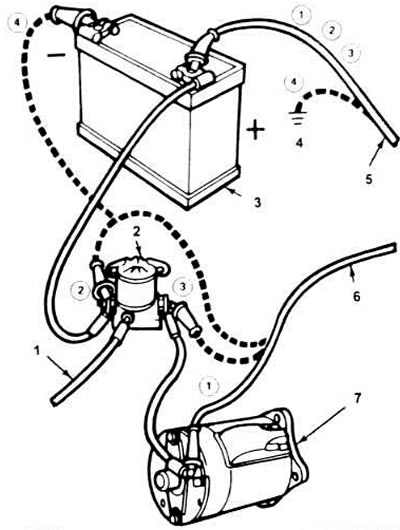
18.12. Four points for connecting contacts when testing the starter circuit.
1. To the ignition key.
2. Relay.
3. Battery.
4. Grounding to the engine.
5. Positive contact of the voltmeter.
6. Negative contact of the voltmeter.
7. Starter.
The numbers in the circles indicate the position of the wires during each of the four tests.
13. When operating the ignition key, take readings from the voltmeter as soon as a certain value is established. The one-time operation of the starter should not exceed 30 seconds.
14. The voltmeter will record the voltage drop in the circuit (set the voltmeter to a measurement range of 0 to 2 volts). The maximum permissible voltage drop values should be:
a) 0.5 volts with the negative wire of the voltmeter connected to the starter contact and the positive wire to the positive contact of the battery (connection 1 in Fig. 18.12).
b) 0.1 volts with the negative lead of the voltmeter connected to the starter relay (on the battery side) and the positive lead to the positive battery terminal (connection 2).
v) 0.3 volts when the negative wire of the voltmeter is connected to the starter relay (from the starter side), and the positive wire is connected to the positive terminal of the battery (connection 3).
g) 0.3 volts when the negative wire of the voltmeter is connected to the negative terminal of the battery and the positive wire is grounded to the engine (connection 4).