Contents: Examination ↳ Replacement ↳
Examination
1. The manufacturer does not regulate the testing of the stator (sensor) of the TFI - IV system. If the system does not work with the normal state of the ignition unit, replace the stator.
Replacement
2. Remove the distributor cap and set it aside along with the wires.
3. Disconnect the TFI module from the wiring.
4. Remove the distributor (see section 7).
5. Remove the runner (if necessary) see chapter 1).
6. Remove the ignition unit (section 9). To protect it from possible damage during the process of disassembling the distributor.
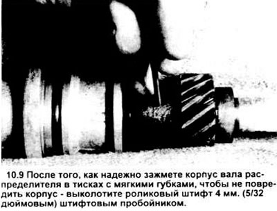
7. Clamp the lower end of the distributor in a vice with soft jaws.
8. When removing the drive gear, remember that the roller pin is slightly offset. When installing the distributor, the roller pin cannot be installed until the holes in the drive gear and the distributor shaft into which it is inserted are completely aligned.
9. Using a 4mm (5/22") punch, tap the roller pin out of the shaft while an assistant holds the distributor in a vice (see illustration).
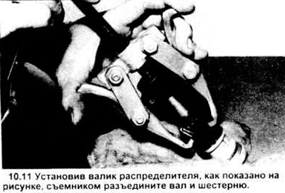
10. Release the vice and position the distributor so that the drive gear is at the top.
11. Using a puller, remove the drive gear (see figure).
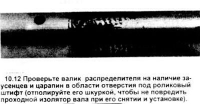
12. Before disconnecting it from the distributor, check the shaft - there may be burrs or scratches from assembly, especially around the hole for the roller pin (see picture). If there are burrs or scratches, polish the roller with sandpaper and wipe it thoroughly so as not to damage the seal lips and the bushing on the base of the distributor.
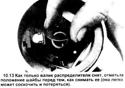
13. After cleaning off any burrs or scratches, remove the roller assembly by pushing it into the plate. Note the position of the intermediate ring washer in relation to the base of the distributor before removing this washer (see figure).
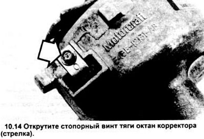
14. Unscrew the octane corrector rod lock screw (see figure).
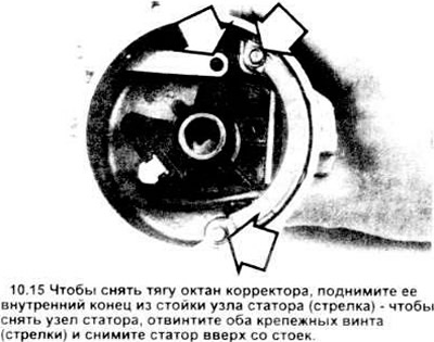
15. Lift the inner end of the rod out of the stator retaining post (see figure) and push the octane corrector rod out of the distributor base.
Note: Do not lose the sealing ring from the rod hole. It protects the distributor components from contamination.
16. Unscrew the two stator screws (see Figure 10.15).
17. Carefully lift the stator assembly straight up and off the distributor.
18. Check the shaft bushing insulation at the base of the distributor for wear and signs of overheating; if there are signs of wear and/or damage, replace the entire distributor assembly.
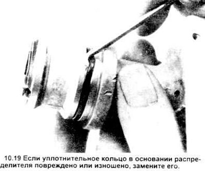
19. Check the sealing ring at the base of the distributor. If it is damaged or worn, remove it and install a new one (see figure).
20. Check the cast housing - there may be cracks, wear. If there is any obvious damage, replace the distributor unit.
21. Place the stator on the shaft bushing and press it into the distributor housing until it fits tightly into its socket.
22. Tighten the stator screws securely.
23. Insert the octane corrector rod into the hole in the base of the distributor, push its inner end into the rack.
Note: Make sure the rod hole is sealed with a sealing ring.
24. Tighten and securely tighten the octane corrector rod screws.
25. Apply a thin coat of engine oil to the distributor shaft and pass the shaft through the bushing.
26. Place the distributor in a vice with the lower end facing up. To protect the base of the distributor, place a clean rag between it and the vice jaws. Place a wooden block under the distributor shaft - it will support the shaft and prevent it from falling out when installing the drive gear.
27. Using the paint marks that were made on the drive gear and the distributor shaft housing, turn the shaft until the hole in the drive (and, accordingly, the paint mark), the hole in the shaft and the paint mark on the distributor shaft are aligned.
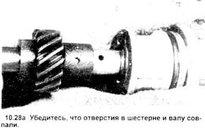
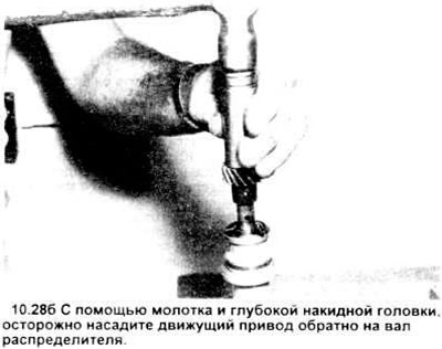
28. Using a hammer and deep socket, carefully seat the drive gear back onto the distributor shaft (see illustration). Make sure the hole in the drive gear and the shaft are aligned. Since the factory drilled these two holes in the same installation, they must be aligned perfectly otherwise the locking pin will not fit (see illustration).
29. Once the gear is firmly seated and the holes are aligned, turn the distributor on its side in the vice and use a 4mm (5/32") punch to install the new pin into the drive.
Make sure that neither end of the pin protrudes from the drive gear.
30. Check the smooth rotation of the distributor shaft, then remove the distributor assembly from the vice.
31. Install the TFI - IV module (see section 9).
32. Install the slider (if necessary) see chapter 1).
33. Install the distributor (see section 7).
The original source of this article can be found at [FordBook]