The cylinder head can be ground no more than 0.3 mm. The combustion chamber volume cannot be less than 38.88 cm³. If these requirements are not met, the cylinder head must be replaced.
Check the camshaft bearing holes for signs of wear. The camshaft should rotate freely in the bearings, without jamming. A warped or damaged cylinder head should be replaced with a new one. Slightly knocked out valve seats can be repaired using the appropriate tool kit (e.g. Hunger). But first, you need to check the valve stem clearance in the guide. The method for this measurement is shown in Fig. 2.70.
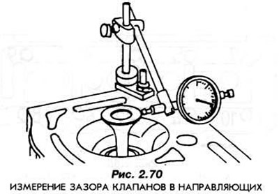
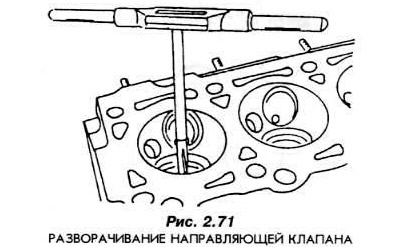
The clearance measured in this way can be a maximum of 0.7 mm for the inlet valve and 0.8 mm for the outlet valve. If the clearance is greater, the guide must be turned to the next repair size (Fig. 2.71). After this, new valves with stems of increased diameters must be selected. The width of the working chamfer of the valve plate must be:
| in 1.4i engines | in engines 1.1 | |
| Intake valves | 1.75 mm | 1.18mm |
| Exhaust valves | 2.32 mm | 1.75 mm |
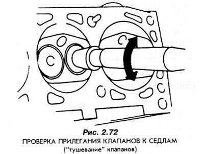
The upper angle of the working chamfer cone of both types of valves is 45°. The angle of the upper correction of the seat is 30°, and the lower correction is 75°. Before inserting into the seat, lubricate the working chamfer of the valve plate with a thin layer of fine-grained abrasive paste for lapping. Insert the valve into the guide and install it in the seat. Turn the valve several times. The mating surface will be visible on the working chamfer of the valve as a matte ring, the width of which should correspond to the values given above. Near the edge of the plate on the surface of the working chamfer, a "shiny ring" 0.5 mm wide should be visible (Fig. 2.72).
Under no circumstances should the valve face be ground separately from the seat. The only way to achieve a precise fit between the face and the seat is by painstaking (and time-consuming) lapping, using appropriate tools.
The cylinder head is installed in the reverse order of dismantling.