Contents: Removal ↳ Installation ↳
Removal
Models produced before 10.1996
Note: This procedure assumes that you are removing the cylinder head with the intake and exhaust manifolds attached to it. This simplifies the procedure, but the assembly being removed is bulky and heavy, so you will need a lift. If you want to remove the manifolds first, follow the instructions paragraphs 6 and 7 this chapter, and then perform the cylinder head removal operations described in this paragraph.
1. Relieve pressure in the fuel system (Chapter 4).
2. Place the vehicle on a firm, level surface, open the hood and disconnect the negative battery cable (Chapter 5, paragraph 1).
3. In any case, when you disconnect vacuum hoses, coolant hoses, ventilation hoses, electrical connectors, wires, ground wires, fuel lines, as required by the following procedure, mark the disconnected parts with tags so that you can reinstall them in their proper places later.
4. Disconnect the two electrical connectors, disconnect the vacuum hose (if equipped), disconnect the crankcase ventilation hose from the cylinder head cover. Remove the air cleaner assembly together with the air flow meter, resonator and pre-chamber (Chapter 4).
5. Equalize the pressure in the fuel tank with the atmospheric pressure by removing its filler cap. Then disconnect the fuel supply and return lines connecting the engine to the chassis (Chapter 4) and plug all the resulting holes.
6. Disconnect the accelerator cable from the throttle actuator (Chapter 4). Also disconnect the cruise control actuator cable (if equipped) (Chapter 12). Secure the cable(s) away from the engine/transmission.
7. Remove the bolts and disconnect the power steering pressure line from the rear head support plate/engine lifting eye and from the pump bracket/front support plate. Release the wire retainer and disconnect the power steering pressure switch wire connector. Then remove the bolt and disconnect the ground strap from the rear head support plate/engine lifting eye.
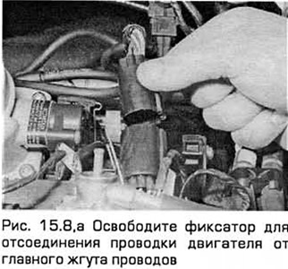
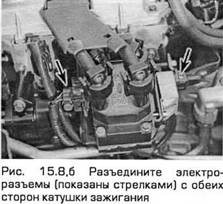
8. Remove the three screws securing the wiring tray to the rear of the manifold. Disconnect the engine wiring from the main wiring harness by disconnecting the large electrical connector (this connector is located next to the fuel pressure regulator) (See Fig. 15.8, a). Disconnect the electrical connectors on each side of the ignition coil, as well as the connector located at the front under the thermostat housing to disconnect the coil and the coolant temperature gauge sensor wiring (See Fig. 15.8, b).
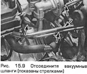
9. Disconnect the vacuum hoses in the following order (label them as you disconnect them):
- a) One - from the back of the throttle body. (Disconnect only one hose. The second hose, which goes to the fuel pressure regulator, does not need to be disconnected.)
- b) One - from the fitting at the opposite end of the intake manifold 9 (see Fig. 14.9).
- c) Brake booster vacuum hose (Chapter 9).
- d) Disconnect all vacuum hoses from the EGR system components - one from the EGR valve and two from the EGR pipeline. Note that the last two hoses have different sizes of nozzles and therefore should not be frightened.
10. Remove the bolts from both parts of the exhaust manifold heat shield. Disconnect the coolant hose to remove the upper part of the housing. Remove the oil level control dipstick together with its pipe or move them to the side.
11. Remove the bolt securing the fuel afterburner filter housing to the front engine/transmission mount bracket. Then disconnect the filter vacuum hose.
12. Drain the cooling system (chapter 1).
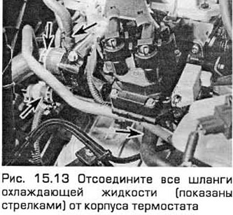
13. Disconnect all coolant hoses from the thermostat housing (see Fig. 15.13).
14. Remove the two nuts and disconnect the exhaust downpipe from the manifold (Chapter 4). Disconnect the oxygen sensor wiring so that it is not strained by the weight of the exhaust system.
15. Remove the accessory drive belt (chapter 1).
16. Support the engine/transmission with a jack, placing a wooden spacer between the jack platform and the oil pan to avoid damaging the oil pan.
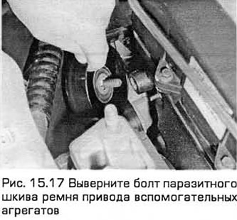
17. Remove the six nuts securing the right engine/transmission bracket, then remove the bracket. Remove the accessory drive belt idler pulley bolt (see Fig. 14.17).
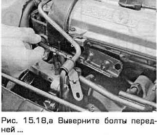
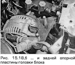
18. Unscrew the bolts of the front and rear support plates of the cylinder head (see Fig. 15.18, a, b).
19. Remove the timing belt and camshafts (paragraph 10 and 13). If you disassemble the cylinder head, remove the hydraulic lifters.
20. Remove the inner timing belt cover (paragraph 9).
21. In the reverse order to that shown in Fig. 14.32, b, loosen the ten cylinder head bolts (loosening each bolt one turn at a time). This will require a slotted head wrench (TX 55). These bolts should always be replaced with new ones after loosening (due to the complex nature of the load they experience).
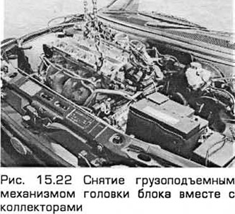
22. Remove the cylinder head with the help of an assistant (if possible), as it is heavy (see Fig. 15.22). Remove the gasket, paying attention to the mounting pins. The gasket can be discarded.
Models produced since 10.1996
23. Disconnect the negative battery cable and drain the cooling system.
24. Apply the parking brake. Raise the front end and place it on supports. Remove the right front wheel.
25. Remove the splash guard from under the engine and the lower radiator shroud. On models produced since 05/1998, unscrew the bolts and remove the accessory belt cover.
26. Place a container under the radiator. Then unscrew the drain plug so that the coolant flows into the container. On models produced since 05.1998, disconnect the coolant hose located under the engine on the right. If necessary see Chapter 1.
27. Remove the right front wheel arch liner.
28. Remove the accessory drive belt (see Chapter 1).
29. On models produced from 05.1998, unscrew the bolt and remove the water pump pulley and idler pulley. Also remove the crankshaft pulley and the lower timing cover (see paragraph 9).
30. On models with 1.6 and 1.8 liter engines, remove the catalytic converter (see Chapter 4A).
31. Disconnect the engine wiring and the brake booster hose from the intake manifold. Also disconnect the positive crankcase ventilation hose from the manifold.
32. Disconnect the oil pressure sensor wiring.
33. Unscrew the central bolt of the rear engine roll limiter. Remove the limiter from the subframe.
34. Unscrew the central bolt of the front engine roll limiter. Unscrew the nuts securing the limiter to the subframe. It will not be possible to remove the limiter yet.
35. Remove the air duct chamber, air duct and air cleaner cover (Chapter 4A).
36. Disconnect the accelerator cable from the segment located on the throttle body. Then pull the plastic clamp and disconnect the cable from the support bracket. Move the cable to the side.
37. Disconnect all vacuum hoses from the intake manifold,
38. Disconnect the wiring from the intake manifold, noting its routing. On models produced since 05/1998, disconnect the wiring channel from the intake manifold.
39. Locate the EGR valve vacuum hoses and disconnect them.
40. Disconnect the wiring from the ignition coil, radio interference suppressor and coolant temperature sensor.
41. Disconnect the wiring from the power steering pressure sensor and disconnect the ground wire from the engine cargo eye. Remove the bolts and bracket for the fuel afterburner pipe. On 05/1998 and later models, remove the oil dipstick tube bolts from the cylinder head.
42. On models with 2.0L engines, remove the air conditioning pipe bracket bolts.
43. Remove the bolts and exhaust manifold heat shield and pull out the engine oil level dipstick.
44. Remove the bolts and disconnect the EGR valve from the exhaust manifold, the EGR pipe from the engine cargo eye and the ignition coil.
45. On models with 2.0 liter engines, unscrew the nuts and disconnect the catalytic converter from the exhaust manifold. Then unscrew the nuts of the fittings and disconnect the pipes of the exhaust gas afterburning system.
46. Release the clamps and disconnect the cooling system hoses from the thermostat housing.
47. Disconnect the wiring from the coolant temperature gauge sensor.
48. On 2.0L models, disconnect the crankshaft position sensor wiring. Then remove the bolts and the afterburner filter.
49. Mark the position of the right engine mount, then support the engine with a jack through a wooden shim. Unscrew the bolts of the right engine mount bracket.
50. Remove the bolts and nuts and remove the hydraulic power steering bracket from the cylinder head. On models produced from 05/1998, remove the bolts of the coolant expansion tank and move it to the side.
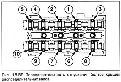
51. Remove the bolts and remove the generator bracket from the cylinder head.
52. Release residual pressure in the fuel system (Chapter 4A).
53. Disconnect the quick-release connections of the fuel supply and outlet hoses.
54. Remove the bolt of the auxiliary drive belt idler pulley. Then remove the upper and then the middle timing cover.
55. Disconnect the high-voltage wires from the spark plugs. Then unscrew the bolts and remove the cylinder head cover.
56. Remove the spark plugs. Pull out the engine oil dipstick.
57. Mark the timing belt to indicate its direction of rotation. Then loosen the tensioner nut and turn the tensioner pulley clockwise with an Allen key. Lock the tensioner in this position by tightening the nut. Remove the belt.
58. Remove the toothed pulleys from the camshafts (paragraph 13).
59. Loosen the camshaft bearing cap bolts in the sequence shown in Fig. 15.59. Unscrew the bolts and remove the bearing caps, camshafts and seals.
60. Remove the valve lifters and place them in a container with cells so that their position can be determined. If the engine has hydraulic clearance compensators, they must be immersed in engine oil.
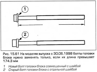
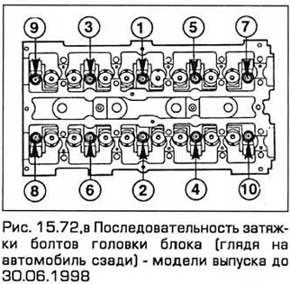
61. In the reverse order to that shown in Fig. 15.72, c, gradually (one turn at a time) loosen the 10 cylinder head bolts. This requires a TX 55 wrench. Remove the bolts and inspect them for damage. It is recommended that the cylinder head bolts are always replaced after they have been loosened. However, on models manufactured from 30.06.1998 onwards, the bolts should only be replaced if their length exceeds 174.3 mm (see Fig. 15.61).
62. Remove the cylinder head with an assistant, as it is heavy. Remove the gasket, noting the position of the pins and discard it.
Installation
64. Check the mating surfaces of the cylinder head and block for dents, deep scratches and other signs of damage. Minor defects can be removed with a file, but in case of significant damage, the damaged surface must be machined or the damaged component must be replaced.
65. If you suspect that the surface under the cylinder head gasket has warped, check it with the end of a metal ruler. If necessary, see Chapter 2B.
66. Clean the mating surfaces of the cylinder head and block. Make sure that the dowel pins are driven into the block and that the cylinder head bolt holes are free of grease.
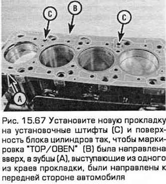
67. Install the new gasket onto the dowel pins and cylinder block surface with the "TOP/OBEN" marking facing upwards and the teeth protruding from one edge of the gasket facing the front of the vehicle (see Fig. 15.67).
68. Temporarily install the crankshaft pulley and turn the shaft counterclockwise so that the piston of cylinder No.1 is before TDC and approximately 20 mm lower to protect the valves from damage during assembly.
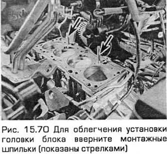
69. The cylinder head together with the manifolds is a bulky and heavy unit. Therefore, it is recommended to make guides for mounting the head. Prepare two studs (M10, 90 mm long) with a slot on one end for a screwdriver. They can be made from old cylinder head bolts by cutting off the heads. Screw these studs with the slot on the end upwards into the bolt holes located in the corners of the cylinder block diagonally to each other (or into the holes intended for the mounting pins). These studs should protrude approximately 70 mm above the gasket.
70. Install the cylinder head onto the mounting studs and seat it onto the mounting pins (see Fig. 15.70). Unscrew the mounting studs.
71. Insert the new cylinder head bolts (but do not lubricate their threads). Tighten the bolts by hand.
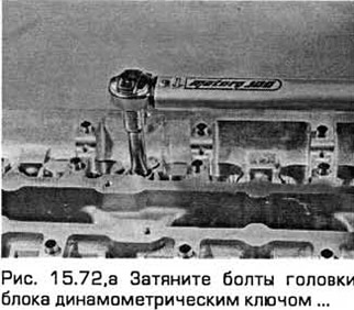
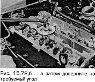
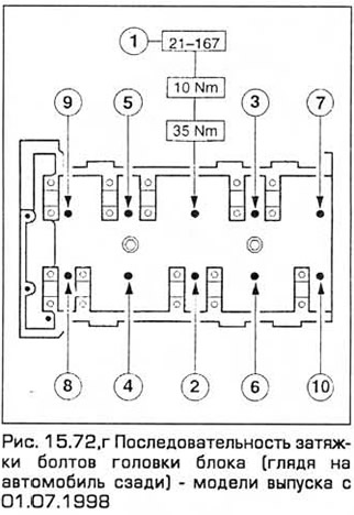
72. In the sequence shown in Fig. 15.72, c, d, tighten the bolts in two steps specified in the Technical Data, first using a torque wrench, and then tighten them to the required angle using a socket and ratchet, as well as a protractor. (see Fig. 15.72, a-g).
Note: After tightening the bolts in accordance with the Technical Data, do not re-tighten the bolts or check their tightness.
73. Install the hydraulic lifters (if removed), camshafts, camshaft seals and pulleys. Temporarily install the crankshaft pulley and turn this shaft clockwise so that the pulley marks are in the position shown in paragraph 10.
74. Install the timing belt and covers, aligning the camshafts (valve timing) and restoring the timing belt tension as specified in paragraph 10.
75. The remaining installation operations are performed in the reverse order of removal, taking into account the following:
- a) Tighten all fasteners to the specified torque.
- b) When installing the right engine/transmission mount, tighten the self-locking nuts and do not allow the mount to rock when tightening the two middle nuts (of six).
- c) Fill the cooling system with liquid and top up the engine with oil.
- d) Immediately after starting and warming up the engine to normal operating temperature, check the joints and connections that were disassembled for oil or coolant leaks.