Contents: Examination ↳ Adjustment ↳
Note: This procedure only applies to models produced after 05/199B. Before this date, Zetec engines were equipped with hydraulic compensator valves.
Examination
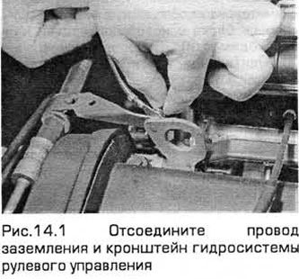
1. Disconnect the negative battery cable. Remove the screw and disconnect the ground wire and the hydraulic steering pipe bracket from the rear engine cargo eye. Move the pipe aside (See Fig. 14.1).
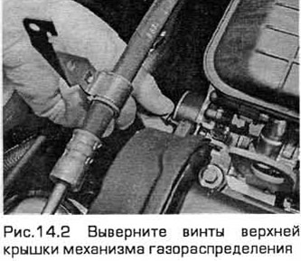
2. Unscrew the bolts securing the upper plastic cover of the valve timing mechanism to the cylinder head (see Fig. 14.2).
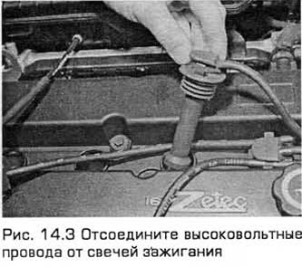
3. Disconnect the high-voltage wires from the spark plugs and move them to the side (see Fig. 14.3).
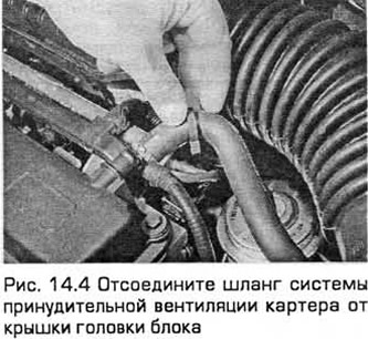
4. Release the clamp and disconnect the positive crankcase ventilation hose from the cylinder head cover (see Fig. 14.4).
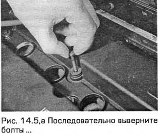
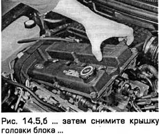
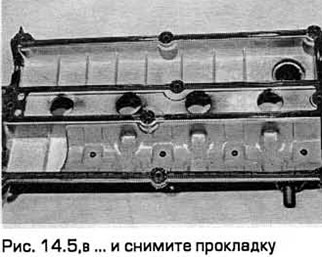
5. Gradually loosen and unscrew the bolts, then remove the cover. Remove the gasket (see Fig. 14.5, a-c).
6. Set the engine to TDC for cylinder #1. The intake and exhaust camshaft lobes should be pointing up (though not exactly vertical) above cylinder #1. The valve clearances can now be measured.
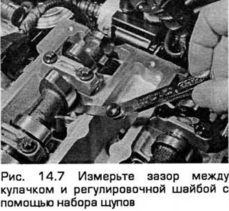
7. Using a set of feeler gauges, measure the clearance between the cam lobe and the adjusting washer on each valve of cylinder No.1 in turn (see Fig. 14.7). Record the thickness of the feeler gauge. The specified clearance values are given in the Technical Data. Keep in mind that the clearances of the intake and exhaust valves are different. The intake camshaft is located at the rear of the engine, and the exhaust camshaft is located at the front. Record all four clearances.
8. Rotate the crankshaft clockwise one half turn so that the cam lobes above cylinder #3 point upward. In this position, measure and record the valve clearances for cylinder #3. The clearances for cylinders #2 and #4 can be measured by rotating the crankshaft one half turn at a time, respectively.
Adjustment
9. If adjustment is necessary, press the pusher and replace the adjusting washer with a washer of a different thickness.
10. Before replacing the washer, the piston of the corresponding cylinder must be lowered and brought to a position shifted by 1/4 turn clockwise relative to TDC. If this is not done, the piston will interfere with the valve movement when pressed, which can cause damage.
11. There is a special Ford tool for pressing the valves. It consists of a bar that is bolted to the top of the cylinder head and a lever with a projection that rests on the edge of the tappet. To avoid damage, it is strongly recommended to use this tool rather than a screwdriver or something similar.
12. Press the plunger and remove the adjusting washer using a small screwdriver or magnet.
13. If the clearance needs to be increased, install a thinner washer. To decrease the clearance, install a thicker washer. The thickness designation is engraved on the side of the washer opposite the camshaft. If it is not visible, measure the thickness with a micrometer.
14. When the gap and thickness of the washer being replaced are known, the thickness of the new washer can be calculated according to the examples:
The gap needs to be increased
Required clearance
(A) = 0.15 mm
Measured gap
(B) = 0.09 mm
Thickness of the replaceable washer
(C) = 2.55 mm
Thickness of the required washer
(D)1 C + B - A = 2.49 mm
The gap needs to be reduced
Required clearance
(A) = 0.30 mm
Measured gap
(B) = 0.36 mm
Thickness of the replaceable washer
(C) = 2.19 mm
Thickness of the required washer
(D) = C + B - A = 2.25 mm
15. After installing the washer of the required thickness, release the tappet pressing device. Turn the crankshaft so that the camshaft cams are directed upward again. Check the clearances.
16. Repeat the procedure for the remaining valves, turning the crankshaft accordingly.
17. It is useful to keep a record of the shim thickness values for each cylinder.
18. It is permissible to reinstall the washers from one tappet to another to achieve the required clearance. However, it is not recommended to turn the camshaft when any adjusting washers are removed.
19. After achieving the required clearances, remove the device and install the cylinder head cover with a new gasket (if necessary). Connect the positive crankcase ventilation hose and high-voltage wires. Install the valve timing cover and tighten its bolts. Connect the negative battery cable.