Contents: Examination ↳ Adjustment ↳
Examination
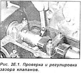
The valve clearance is checked with a feeler gauge between the rear of the cam and the tappet (see Fig. 2E.1).
Disconnect the flexible crankcase ventilation hose from the cylinder head cover. Remove the cylinder block cover. Turn the engine crankshaft by the pulley mounting nut (do not turn by the camshaft pulley) in the direction of its working rotation to a position in which both cams of cylinder 1 are turned with the working part of the cam upward. Check the valve clearance of cylinder 1 by inserting a feeler gauge plate between the rear of the cam and the tappet. Determine the type of valve being checked (inlet or outlet) and compare the measured clearance value with the required value. Adjust the clearance of the valve being checked, if necessary.
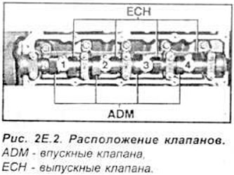
Attention. The sequence of valve installation, counting from the front of the engine (from the side of the timing drive), is the same in each cylinder: the first (near the timing drive) is the intake valve and the second is the exhaust valve.
Repeat the described steps for the valves of the remaining cylinders in the injection sequence (1 - 3 - 4 - 2, counting from the valve timing drive side).
Adjustment
Adjusting the valve clearance consists of replacing the adjusting plate located in the tappet recess. Replacing the adjusting plates does not require removing the camshaft if a special device is used to perform this operation.
Attention. When replacing the valve clearance adjusting plates, the engine pistons should not be exactly at TDC, but a few millimeters lower (about 1/4 of a crankshaft revolution). This will prevent the valve from hitting the bottom of the piston when pressing the adjusting plate.
Turn the tappets so that after compression, special pliers for removing the adjusting plates can be easily inserted into the cutouts in the tappet bottoms. Set the engine crankshaft to the appropriate position and, using the pressure device (tool 21 106), press the tappet down (opening the valve and compressing its spring at the same time) so that, using special pliers (21 107), the adjusting plate can be removed.
Measure the thickness of the removed plate and, taking into account the measured clearance and the required nominal value, select a plate from the kit with a thickness that provides the required valve clearance. Insert the selected plate so that the surface with its designation is directed downwards (towards the tappet).
Remove the pressure device. Repeat the described operations for the remaining valves. Install the cylinder head cover with a new gasket. Attach the flexible pipe of the engine crankcase ventilation system to the cylinder head cover. Since March 1992, the engine cylinder head cover is cast from light metal. In addition, an oil deflector is installed under the engine cylinder block cover (see Fig. 2E.3). which improves lubrication of the camshaft.
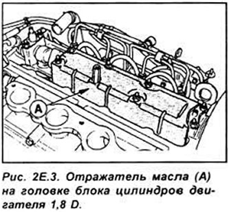
After removing the cylinder head cover, before adjusting the valve clearance, unscrew the oil deflector mounting nuts and remove the oil deflector and tighten the mounting nuts.
Check and adjust valve clearance if necessary.
Unscrew the nuts again, install the removed oil deflector and tighten the fastening nuts again (see Fig. 2E.3).
[This publication was borrowed from the website: www.FordBook.ru]