General information
1. These supports do not often require attention, however, a destroyed or broken support must be replaced immediately. Otherwise, the loads generated in the power train may cause damage or wear.
2. Supports can be removed and installed individually. If you need to disassemble several supports, such as when removing the power unit, then this removal and installation procedure must be performed in a clear sequence.
3. During installation, the weight of the power block must not be transferred to the supports until they are all properly aligned. Install a Ford special tool instead of the front support and tighten the fasteners of the power unit support to the required torque in the sequence specified in paragraphs. 49-50 paragraph 4 ch. 2B.
Inspection
4. When inspecting the power unit, you need to slightly raise it so that its weight is not transferred to the supports.
5. Raise the front of the car and place it on supports. Install the jack under the pallet and, having laid a wooden gasket between it and the jack head, support the power unit for hanging it.
Warning: If the engine is only supported by a jack, do not work under it!
6. Inspect the supports for rubber cracks, hardening or separation of the rubber from the metal part. Sometimes the rubber cracks just below the center.
7. Check the possibility of relative displacement of the bracket of each support and the power unit or body. To do this, move the supports with a power screwdriver or lever. If the displacement is noticeable, lower the engine and check the tightening (torque wrench) support fasteners.
Replacement
Note: The following assumes the engine is jacked up (as mentioned above).
Front support (roll limiter)
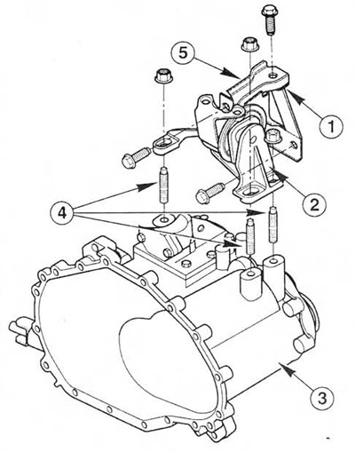
8. Remove the resonator support bracket bolts from the engine compartment front cross member. Loosen the two screws of the clamps that secure the resonator to the hoses of the air flow meter and prechamber. Then move the resonator away from the thermostat housing (see ch. 4). Turn out bolts of the case of the filter of system of afterburning of fuel from an arm of a support. Then turn out bolts/nuts of fastening of a support to a stretcher. Loosen the center bolt and remove the support. Note the position of the wiring connector bracket. If necessary, the support bracket can be removed from the transmission by unscrewing its bolts (see fig. 23.8).
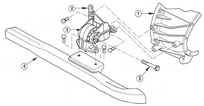 Pic. 23.8 Power unit front support (manual transmission shown, automatic transmission similar)
1. Transmission
2. Support bracket
3. Support
4. Front suspension subframe
5. Support center bolt
9. When installing, securely tighten the bolts securing the support to the transmission, and then install the support and wiring connector bracket. Torque tighten first (in two stages) bolts and nuts securing the support to the subframe. After that tighten the central bolt of a support by the demanded moment.
Right support
10. Unscrew the nuts and remove the bracket, taking into account which of the nuts are self-locking (after unscrewing, they must always be replaced). Remove the mounting bolts from the body (see fig. 23.10).
 Pic. 23.10 Right power block support (conventional type)
1. Bracket
2. Support
3. Brackets bolted to cylinder block/crankcase
4. Body
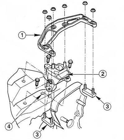
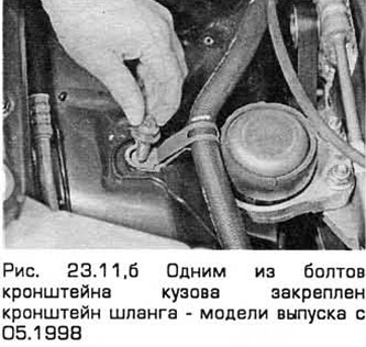
11. In the case of installing a hydraulic support, the bracket is fixed with five nuts. In this case, the support can be recognized by its shape. It should never deviate more than 5°from the vertical (see fig. 23.11). On production models from 05.1998, the transverse bracket is not installed, and one of the body bracket mounting bolts is also fixed to the cooling system hose bracket (see fig.23.11, b).
 Pic. 23.11, a. Right support of the power unit (hydrosupport)
1. Bracket
2. Hydro bearing
3. Brackets bolted to cylinder block/crankcase
4. Body
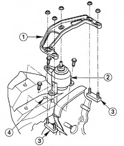
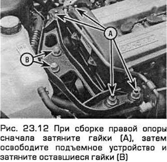
12. When installing, replace the self-locking nuts and tighten the fasteners to the correct torque. When tightening the nuts, first tighten the four nuts securing the bracket to the engine, then lower the power unit by the lifting mechanism onto its supports. When tightening the remaining two nuts, the support must not oscillate (see fig. 23.12).
Left support
13. Disconnect the two wiring connectors, disconnect the vacuum hose (if available), disconnect the crankcase ventilation hose from the head cover and remove the air cleaner assembly together with the air mass meter, resonator and prechamber (chapter 4).
14. Remove the three nuts to release the mount from the transmission and then remove the mount bolts from the body (see fig. 23.14). Please note that nuts are self-locking and should always be replaced after loosening. Turn out the central bolt for dismantling of a support and if necessary replace with components.
 Pic. 23.14 Left power block support (manual transmission shown, automatic transmission similar)
1. Support bracket
2. Support
3. Transmission
4. Studs
5. Mounting plate (in the presence of)
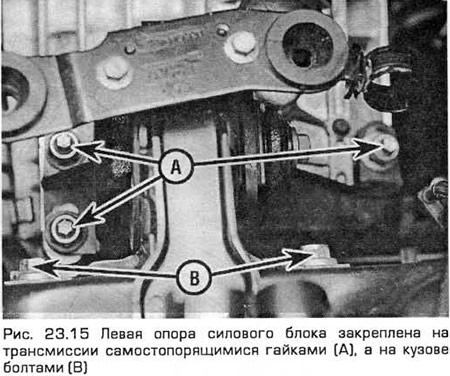
15. When installing, replace the self-locking nuts. When tightening the nuts, do not let the support swing (see fig. 23.15). Tighten all fasteners to the required torque.
Rear support (roll limiter)
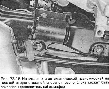
16. On models with automatic transmission, a separate damper can be installed under the subframe, the bolts of which must be unscrewed to get to the support fasteners (see fig. 23.16).
17. Turn out bolts of a support from a stretcher. Then turn out the central bolt of a support. If necessary, remove the support bracket bolts from the transmission (see fig. 22.17, a, b).
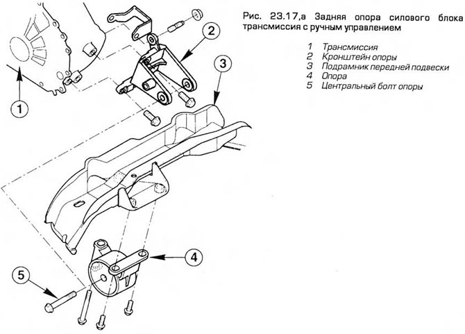
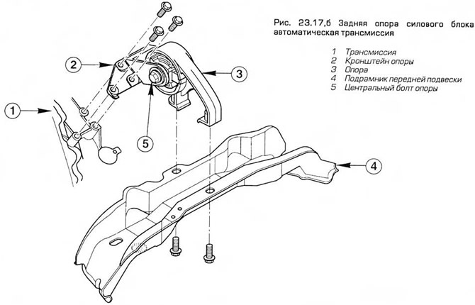
18. At installation reliably tighten bolts of fastening of an arm of a support to transmission. And then install the support. First tighten the bolts securing the support to the subframe (in two stages by the required moment). After that, tighten the central bolt of the support to the required torque.
Visitor comments