Removal
1. Remove the valve cover (section 3).
2. Loosen and then remove the valve lifter mounting bolts, starting from the front of the cylinder head.
3. Remove the valve levers, pivot pins and pushrods and store them together with their mounting bolts. Store each valve kit separately so that each part will fall into place when installed.
4 Remove the push rods and store them separately to avoid confusion during installation.
Examination
5. Inspect each valve lever for wear, cracks, or other damage, especially where they contact the pushrods and valve stems. In each lever, inspect the pivot pin seats and the appearance of the pivot pins themselves (see illustration). Look for binding, stress cracks, and unusual wear patterns. If a valve lever is worn or damaged, replace it with a new one and replace the pivot pin as well.
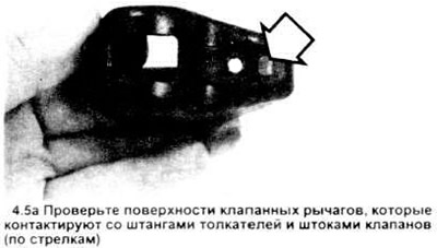
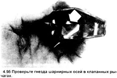
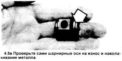
6. Make sure the oil hole at the end of each valve lifter rod is open.
7. Check the push rods for cracks and excessive wear on the ends. Roll each rod on the surface of a glass plate to determine if it is bent (if it vibrates, it is bent).
Installation
8. Lubricate the bottom end of each rod with clean motor oil or moth-based grease and install it in place. Ensure that the rods fit snugly in the sockets.
9. Bring piston No.1 to the top dead center position of the compression stroke (section 5).
10. Apply moly grease to the ends of the valve stems and to the upper ends of the rods before installing the valve levers in place.
11. Install both valve levers of cylinder No.1 (see figure), the inlet valve lever of cylinder No.2, and the outlet valve lever of cylinder No.3; then install the pivot pins and bolts. Apply moly grease to the pivot pins to prevent damage to their mating surfaces before they are exposed to engine oil. Tighten the bolts to the specified torque.
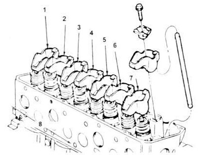
4.11. Valve levers assembly - sectional view
1. No.4 inlet
2. No.4 exhaust
3. No.3 inlet
4. No.3 exhaust
5. No.2 exhaust.
6. No.2 inlet
7. No.1 exhaust
8. Front of the engine.
12. Rotate the crankshaft 180 degrees in the direction of its rotation until piston #4 reaches the dead center of the compression stroke. The distributor rotor should point toward terminal #4 on the cover (if the cover is removed, the rotor should point toward the engine block).
13. Install the remaining valve levers and pivot pins and tighten the bolts to the specified torque.
14. Install the valve cover (section 3).
15. Start the engine, listen for valve knocking, check for possible oil leaks and the valve cover assembly.