Engines: ONS 2.4L V6 2.8L Diesel up to 8/94 V6 2.9L without catalytic converter
To compensate for various thermal expansions, certain clearances must be provided in the valve actuator.
If the gaps are too small, the valve timing changes, poor compression occurs, engine power drops, and its operation becomes uneven. In extreme cases, valves can warp or burn out, as well as valve seats.
If the gaps are too large, a strong mechanical noise will occur. the valve timing changes, due to the shorter valve opening time and the poor filling of the cylinders for this reason, the engine power drops, its operation becomes uneven.
The valve clearances of these engines must be checked and, if necessary, adjusted as part of maintenance and after repairs.
Note: For DOHC engines and all other engines built since 9/94 (SCORPIO II). clearances in the valve drive are maintained unchanged by hydraulic compensators and do not require adjustment.
Valve clearances are checked and adjusted accordingly when the engine is cold (at ambient temperature +20°С).
Adjusting the clearances in the valve drive gives a positive result only if they fit perfectly on the seats, there are no too large gaps in the guides, and when the ends of the valve stems are not broken.
ONS engine
Remove the air filter see p. 57.
Remove spark plug caps.
Remove cylinder head cover.
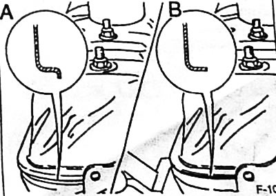
Apply the handbrake, shift the transmission to neutral. Turn the engine crankshaft at the central bolt of the belt pulley in the direction of its rotation so that the camshaft cam at the corresponding valve points upwards.
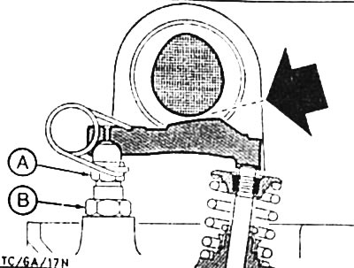
The play in the valve actuator is measured using a feeler gauge between the cam and the pressure lever -arrow-. The probe should pass into the gap, while firmly touching both parts.
Caution: Do not confuse intake and exhaust valves.
- Inlet valve clearance (E): 0.20±0.03mm
- Exhaust valve clearance (A): 0.25±0.03mm
If the gap does not correspond to the prescribed value, it must be adjusted using the adjusting screw with a spherical head -A- (drawing TC/6A/17N).
Holding with a special key (HAZET 3429) spherical head bolt -A-, flat wrench (HAZET 3429-5) loosen locknut -B- (drawing TC/6A/17N). Then turn the socket head bolt as follows. so that the gap reaches the prescribed value. Then, while holding the spherical head bolt, tighten the lock nut to 55 Nm.
Check valve clearances again.
Fit the cylinder head cover with a new gasket and tighten the mounting bolts in the correct sequence to the specified torque, see p. 15.
Engines: 2.4L displacement, 2.8L V6, 2.9L V6 without catalytic converter
Remove the air filter together with the suction hose, see p. 59.
Remove spark plug caps.
Remove cylinder head cover.
Apply the handbrake, shift the transmission to neutral. Turn the engine crankshaft by the central bolt of the belt pulley in the direction of its rotation so that the TDC mark "0" on the pulley coincided with the mark on the crankcase.
Make 3 marks on the belt pulley with chalk at 120°intervals.
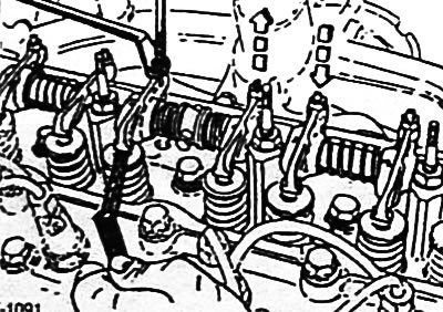
By turning the crankshaft slightly back and forth, check whether the valves of cylinders 1 or 5 are in the overlapping phase. This means that the exhaust valve is closing right now (it moves up), and the inlet valve is opening right now (he's moving down).
Turning the crankshaft 120°each time and following the sequence below, check or adjust the valve clearances accordingly.
- 5th cylinder: overlap - 1st cylinder: adjustment
- 3rd cylinder: overlap - 4th cylinder: adjustment
- 6th cylinder: overlapping - 2nd cylinder: adjustment
- 1st cylinder: overlap - 5th cylinder: adjustment
- 4th cylinder: overlap - 3rd cylinder: adjustment
- 2nd cylinder: overlap - 6th cylinder: adjustment
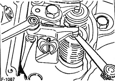
The clearance in the valve actuator is measured using a feeler gauge between the rocker arm and the valve. The probe should pass into the gap, while firmly touching both parts.
Caution: Do not confuse intake and exhaust valves.
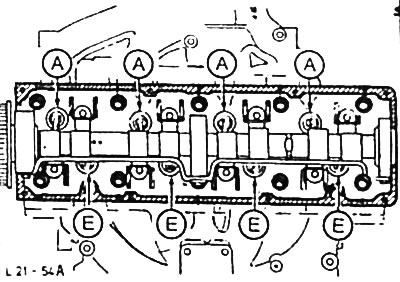
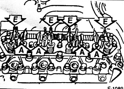
Location of intake and exhaust valves:

- Inlet valve clearance (E): 0.35 mm
- Exhaust valve clearance (A): 0.40 mm
If the gap is not as specified, loosen the lock nut and adjust the gap using the adjusting screw on the rocker arm.
Tighten the locknut.
Check valve clearances again.
Attach the cylinder head cover with a new gasket and tighten the mounting bolts.
Diesel engine up to 8/94
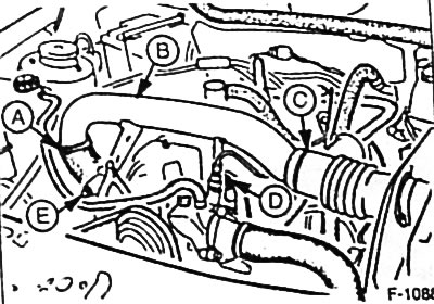
Turbocharged diesel engine Loosen clamps and detach suction hose -A- at turbocharger and connecting air hose -C-. Remove securing nut -C- on cylinder head, securing bolt -E- on intake manifold and remove intake manifold -B-.
Naturally aspirated diesel engine remove the air filter.
Remove cylinder head cover.
Attention. From 10/87 a new cylinder head cover with a reusable silicone seal is installed. The cover is recognizable by the lack of ribbed sealing surface -B-. Therefore, when removing the cover, make sure that the silicone gasket is not damaged.
Apply the handbrake, shift the transmission to neutral. Turn the engine crankshaft by the central bolt of the belt pulley in the direction of its rotation so that the TDC mark "0" on the pulley coincided with the mark on the crankcase.
By turning the crankshaft slightly back and forth, check whether the valves of cylinders 1 or 4 are in the overlapping phase. This means that the exhaust valve is closing right now (it moves up), and the inlet valve is opening right now (he's moving down).
Turning the crankshaft each time after checking the clearance and following the sequence below, check or adjust the clearances in the valve drive of other cylinders accordingly.
- 1st cylinder: overlap - 4th cylinder: adjustment
- 3rd cylinder: overlap - 2nd cylinder: adjustment
- 4th cylinder: overlap - 1st cylinder: adjustment
- 2nd cylinder: overlap - 3rd cylinder: adjustment
The clearance in the valve actuator is measured using a feeler gauge between the rocker arm and the valve. The probe should pass into the gap, while firmly touching both parts.
Caution: Do not confuse intake and exhaust valves.
Inlet valve clearance (E):
- naturally aspirated engine: 0.30-0.35mm
- supercharged engine: 0.10-0.20mm
Exhaust valve clearance (A):
- naturally aspirated engine: 0.30-0.35mm
- supercharged engine: 0.20-0.30mm
If the gap is not as specified, loosen the lock nut and adjust the gap using the adjusting screw on the rocker arm.
Tighten the locknut.
Check valve clearances again.
Model up to 9/87: fit the cylinder head cover with a new gasket.
Model from 10/87: fit cylinder head cover with reusable gasket.
Tighten the cylinder head cover bolts to 3 Nm.
Visitor comments