- install the engine and drive on a car jack, ask an assistant to support the engine and drive well and move them to the required position in the engine compartment;
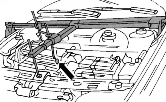
Fig. 34. Device for lifting the engine and drive when hanging the engine
- install a lifting device as shown in Fig. 34. If it is not available, a lifting mechanism with a cable in the eye can be used. It is important that the engine can be lifted until it is connected to the suspension supports;
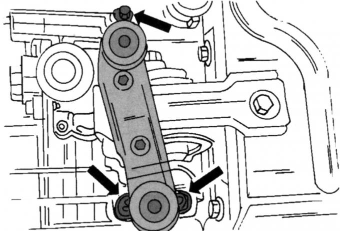
Fig. 33. Left suspension mounting locations on the drive
- secure the left engine mount (see Fig. 33) to the gearbox without tightening the nuts. Always replace the nuts with new ones;
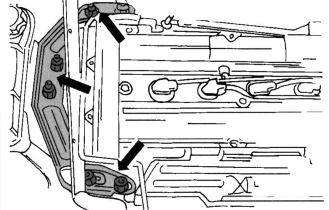
Fig. 32. Right engine mount mounting locations
- install the right engine mount (see Fig. 32). Do not tighten the nuts;
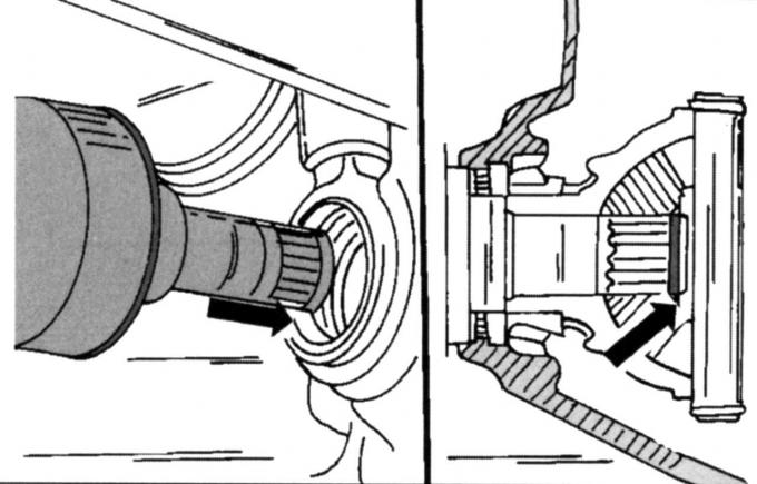
Fig. 35. Installing the left drive shaft. Location of the safety ring
- Install the left drive shaft into the gearbox. Correctly install the new snap ring into the shaft groove before the end of the shaft is inserted into the gearbox (Fig. 35);
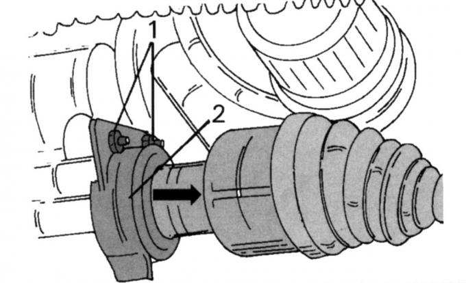
Fig. 30. Removing the right wheel drive shaft: 1 — thrust ball bearing screw; 2 - heat shield
- slide the right drive shaft into the gearbox, install the thrust bearing and tighten both screws 1, shown in Fig. 30, to a torque of 27 N·m. Then install the heat shield 2;
- Insert and secure the low pressure hose of the brake booster into the quick release. Pull the hose to make sure it is securely fastened;
- install the air conditioning compressor, if installed (tighten the four screws to 25 Nm) and insert the electromagnetic clutch plug;
- connect the heating hose to the heating pipe, and the lower radiator hose to the branch pipe and secure it to the heating pipe with a clamp;
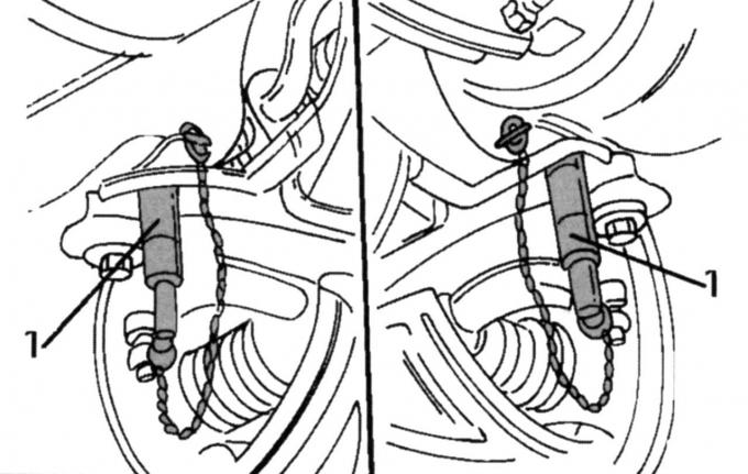
Fig. 36. Using guide pins to center the subframe
- lift the subframe, but first remove the radiator fasteners and the front anti-rotation stop from the subframe. Now install both guide pins 1 (Fig. 36) in the indicated places and align the subframe so that the guide pins are installed in the middle of the holes in the body. Also install the steering in the desired position. Fig. 37 shows from below where the inserted pins are located. If you do not have pins at your disposal, you must mount the subframe according to the previously made markings. Tighten the screws indicated in Fig. 37 evenly to a torque of 130 Nm and unscrew both guide pins 1 again, if they are used;
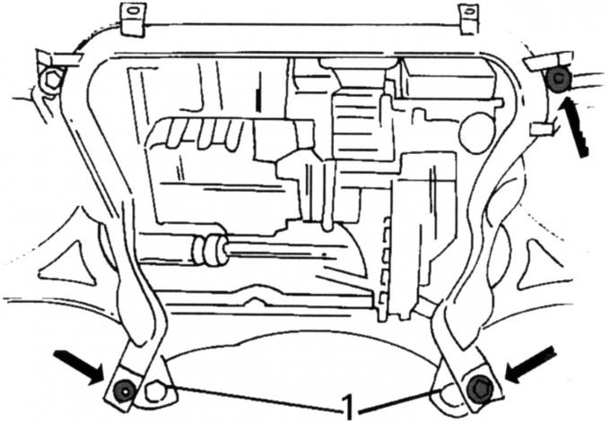
Fig. 37. Location of screws (indicated by arrows) of the subframe: 1 - guide pins
- insert the middle screw of the front stop against rotation, without tightening the nut tightly;
- tighten the three nuts shown in Fig. 33 to a torque of 83 Nm. The engine mount should not twist during this process;
- tighten the nuts (see Fig. 32). First tighten the four nuts on the engine. Tighten both nuts of the suspension bracket after the weight of the engine has loaded the suspension, i.e. the lifting device used must first be removed. The tightening torque for all nuts is 83 N·m;
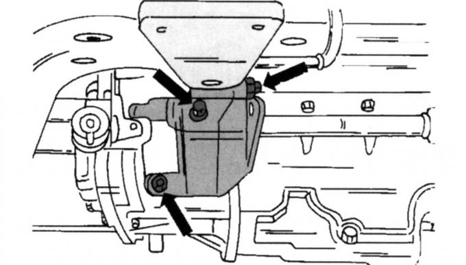
Fig. 29. Location of console mounting screws
- install the rear anti-rotation stop console on the gearbox and tighten to 84 Nm (see Fig. 29);
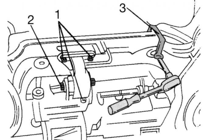
Fig. 38. Fastening the rear anti-spin stop and steering (tightening torques: 1 - 48 Nm); 2 — 120 Nm; 3 — 130 Nm)
- secure the rear torque stop and steering to the subframe as shown in Fig. 38. The figure also shows a special key for tightening the steering screws. Tighten the front torque stop to 120 Nm.
The remaining work is carried out in the reverse order of removal:
- attach the gearbox mechanism to the bottom of the body with a torque of 44 Nm;
- tighten the clutch rod clamping screw to 23 N·m and the support rod mounting screw to 55 N·m. The gearbox must be set to neutral. Align the clamp according to the marking and tighten the clamping screw to 16 N·m. Check later whether the gears shift freely. Fill the gearbox with oil;
- install the front wheel suspension (see the relevant chapter);
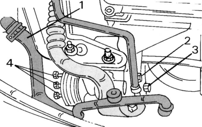
Fig. 28. Fastening of auxiliary steering pump: 1 — hose; 2 - fastening clamps; 3, 4 - mounting screws
- as shown in Fig. 28, tighten screws 3 and 4 to a torque of 47 N·m. Reinstall the clamp and connect the hose to the expansion tank of the cooling system;
- tighten the ground cable fastening between the gearbox and the body to a torque of 47 Nm;
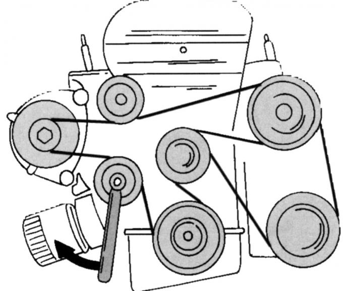
Fig. 39. Direction of rotation of the tension roller when installing the belt
- put on the drive belt according to Fig. 39 and adjust the tension with the tensioner in the direction of the arrow;
- install the exhaust system on the rubber rings and tighten the connection on the exhaust manifold to a torque of 40 Nm;
- connect the fuel lines using quick-release fasteners. The wiring is color-coded;
- after lowering the vehicle onto its wheels, tighten the wheel nuts to a torque of 85 Nm.
This article is a copy from the website FordBook