On vehicles with automatic transmission, the engine is removed without the transmission. Removal of engines installed before May 1998 (vehicles with manual transmission) run in the following order:
- Loosen the nuts securing both front wheels;
- Disconnect both cables from the storage battery and all wires attached to it. Cable connectors in bundles must be cut accordingly, and replaced with new ones when installed;
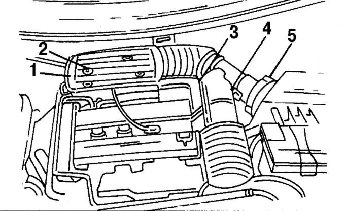
Pic. 22. Fixing the air intake pipes: 1 - mounting bolts, 2 - plug, 3 - plug, 4 - clamp, 5 - low pressure hose
- remove the suction pipe, for which first remove the four bolts 1 (pic. 22) mounts. Then remove the plug 3 from the sensor and release it on the same side, remove the hose clamps 4. Remove the multi-pin plug 2 of the intake air sensor. On the left side there is a reduced pressure hose 5. Take it off;
- Remove the air filter. To do this, disconnect the air supply hose between the filter and the cylinder head cover. Unhook the rubber ring on the right and lift the air filter on the right side out of the holder, take it on the left and remove it;
- Squeeze the plastic clips and remove the hoses from the fuel lines;
- remove the throttle cable safety clip, disengage the throttle cable lever and carefully move the entire cable back;
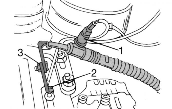
Pic. 23. Disconnecting the steering hose: 1 - plug, 2 - cable, 3 - hose
- take out the plug socket of the push-button switch of the steering mechanism 1 (pic. 23) with amplifier. Unscrew the cable «mass» 2 from the engine lug and disconnect the high pressure hose for the auxiliary power steering pump 3;
- disconnect the various low-pressure hoses by making marks with a felt-tip pen at the end of the hose and the connecting pipe. The hoses are connected to the following parts: one hose is connected to the intake pipe, the other is connected to the fuel pressure regulator. The hose attached to the diaphragm belongs to the exhaust gas recirculation system, both hoses located below belong to the Pulse-Air system. Remove the next hose from the engine purge valve;
- put the front of the car on supports;
- Substitute a suitable container under the front of the car and unscrew the safety shield under the radiator. Open the radiator drain cock. Drain the escaping coolant into a container;
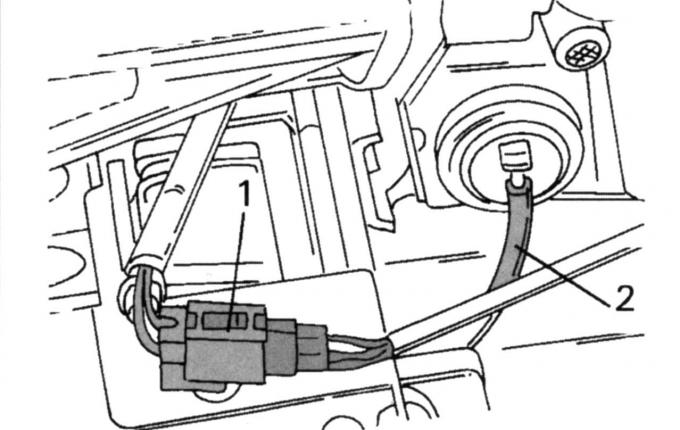
Pic. 24. Disconnecting the multi-pin connector (1) from the lambda probe and hose 2 from the filter of the Pulse-Air system
- remove the multi-pin connector 1 (pic. 24) from the lambda probe and release from the mount. Remove the low pressure hose 2 located in the immediate vicinity. It is connected to the Pulse-Air system filter;
- Remove system of release of the fulfilled gases in gathering. To do this, unscrew the pipe from the exhaust manifold and remove the rest of the system from the rubber suspensions;
- Remove both forward wheels. On the side of the engine belt pulley, unscrew the shield in the wheel well and remove the belt pulley guard;
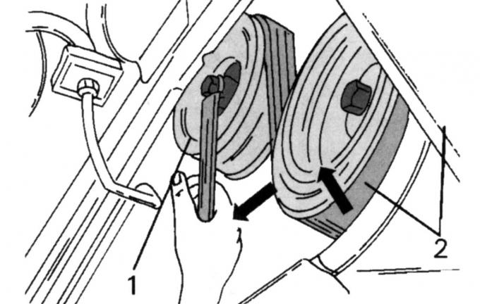
Pic. 25. Loosening the belt tensioner: 1 - tensioner, 2 - drive belt
- loosen tensioner 1 (pic. 25) drive belt just enough to remove it from the pulley. After that, temporarily screw the wheels back on and lower the car to the ground;
- find the cable «masses» between body and gearbox. It is laid near one of the gearbox suspensions;
- remove the clutch control cable from the clutch release lever, release it from the heel and press it to the side;
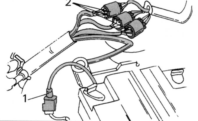
Pic. 26. Disconnecting plug connectors
- open plug 1 (pic. 26). Mark the three plug connectors 2 before removing the main engine wiring harness;
- Release the steering fluid reservoir from the mounting clip;
- Disconnect the multi-pin connector of the engine wiring harness from the module. The plug is fixed in the middle with a screw. Disconnect the nearby wire on the left «masses»;
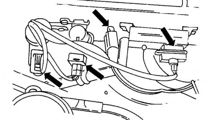
Pic. 27. Location of plug connectors on the front wall of the engine compartment
- unplug the connectors (pic. 27). They also connect to the main engine wiring harness and are located on the front wall of the body;
- Turn away a thermoprotective guard of a final collector;
- Tie the radiator firmly to the engine hood support and disconnect the coolant hoses from the thermostat housing. If necessary, you can cut the clamps if there are difficulties with their removal;
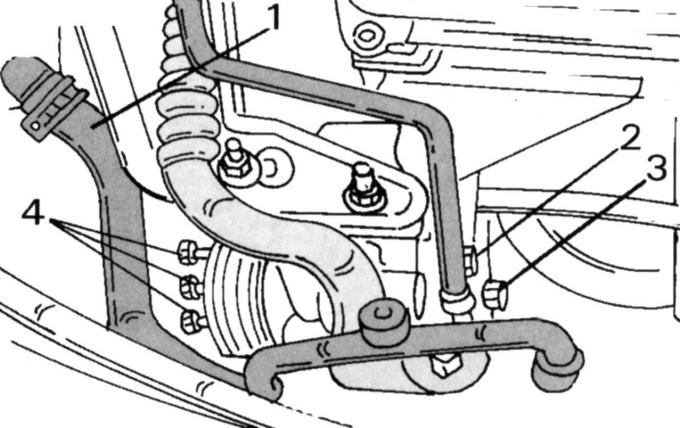
Pic. 28. Attachment of the auxiliary steering pump: 1 - hose; 2 - mounting clamps; 3, 4 - fixing screws
- Release from fastening the auxiliary pump of a steering. To do this, first disconnect hose 1 (pic. 28) from the expansion tank of the cooling system. On the right side, remove the fastening clamp 2 of the high-pressure pipe of the pump, remove the screws (3 and 4) and lay the pump on its side;
- put the front of the car on supports again;
- Disconnect the ball joint to the left and to the right of the lower part of the steering knuckle. In this case, it is necessary to disconnect the system of rods and levers of the anti-roll bar (from the chassis shock absorber) and steering linkage linkage (from the rudder bipod);
- Disconnect the control rod and support rod from the gearbox. The control rod clamp must also be loosened so that the control rod can be pulled out after the clamp screw is loosened. Mark the collar on the pull. Unscrew the support rod;
- unscrew the heat shield and the guide console of the shift handle in the lower part of the car. Pull the entire switching mechanism back and tie with a rope;
- unscrew the steering and the back stop of the engine against turning from the subframe. The steering screws are difficult to reach, so a specially bent wrench must be used for this;
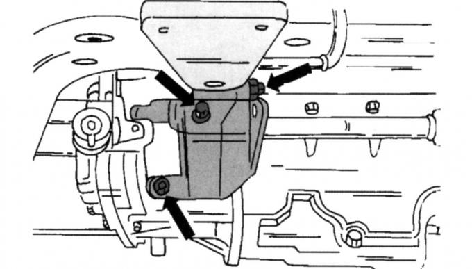
Pic. 29. Location of the console fixing screws
- loosen the three fixing screws shown in fig. 29, and remove the rear stop console from the gearbox;
- Turn out the average screw from a forward stop against turning of the engine;
- Remove the holder of a radiator;
- unscrew the four screws securing the subframe and drain the oil from the gearbox;
Note: Accurately mark the installation position of the subframe before removing it.
- disconnect the heating hose from the heating pipe, remove the lower radiator hose and the heating pipe fixing collar;
- if an air conditioner is installed, remove the compressor screws, remove the electromagnetic clutch plug and remove the compressor. Tie it with a wire to the chassis;
- Disconnect the brake booster low pressure hose from the intake manifold pipe. To do this, the clutch of the quick-release fastener must be open while it is pressed against the connecting element and the hose is pulled out;
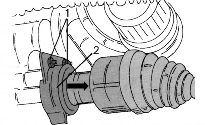
Pic. 30. Removing the right wheel drive shaft: 1 - thrust ball bearing screw; 2 - thermal shield
- Remove the right wheel drive shaft. It is guided by a thrust bearing. After loosening screws 1 (pic. thirty) and unscrewing the heat shield 2, the shaft can be removed from the gearbox. Tie the shaft with a wire to the suspension without creating a large angle in the CV joint;
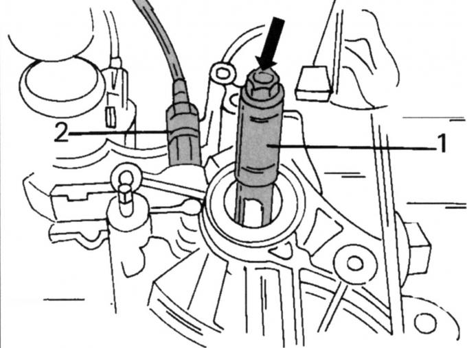
Pic. 31. Removing the left drive shaft and speedometer drive: 1 - mandrel; 2 - nut
- a special mandrel 1 is used to remove the left wheel drive shaft (pic. 31). Using it, knock out the shaft from the seat and then remove it from the gearbox. Tie the shaft with a wire to the suspension without creating a large angle in the constant velocity joint. The same figure shows the speedometer drive. Unscrew the knurled nut 2 and remove the drive;
- put the car jack under the engine/drive (with wooden spacer between car jack head and engine/drive) and raise the unit in suspensions;
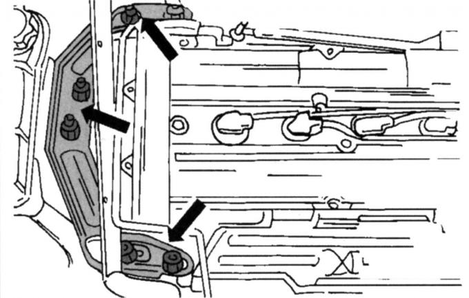
Pic. 32. Attachment points of the right engine mount
- Remove the right engine mount. On fig. 32 shows how the suspension bracket is strengthened. Unscrew the six self-locking nuts (they should always be replaced with new ones). After that, remove the bracket;
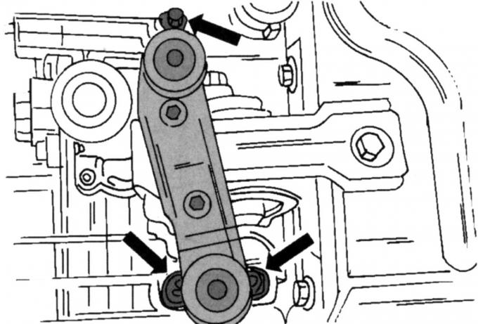
Pic. 33. Attachment points of the left suspension on the drive
- on the opposite side, unscrew the six self-locking nuts of the left drive suspension. Nuts can be thrown away immediately. On fig. 33 shows the mount;
- check that the engine and drive are firmly installed on the jack, and carefully remove them from the car. At the same time, always make sure that the wires and hoses are disconnected.
Visitor comments