Install the chain tensioner.
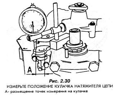
Measure the parallelism of the tensioner cam to the end surface of the engine housing (Fig. 2.30). The difference in distances at the measured points on the cam to the end surface of the engine housing should not be more than 0.2 mm.
Tension the spring and install the tensioner arm on the pin located in the main bearing cap.
Loosen the chain tensioner spring.
Attach the chain gear to the crankshaft. Screw in the central bolt with a washer that secures it.
Install the pushers by inserting them from below into the holes in the body.
Install the camshaft and align it with the axis using the mounting plate.
Secure the bolts that secure the mounting plate with a washer by bending its edges and pressing them against the bolt heads.
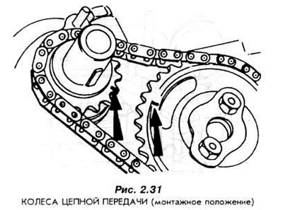
Install the gear together with the chain onto the camshaft. The marks on the crankshaft and camshaft gears should be in line if the chain branch transmitting the drive force is taut (Fig. 2.31).
Secure the gear to the camshaft.
Install the oil deflector on the crankshaft journal.
Install the front cover with a new seal.
Center the cover using the V-belt pulley. Do this before tightening the cover bolts.
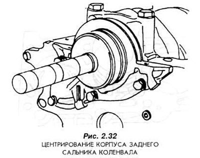
Center the crankshaft rear oil seal housing. The housing should contain a new oil seal and tool 21-103 (Fig. 2.32).
Screw the housing with the mounting bolts.
Place the rubber oil pan gasket on the engine housing flange
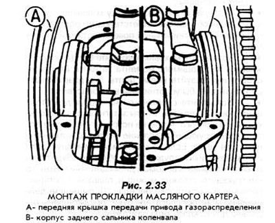
Lubricate the surface of the engine housing with silicone sealant where the oil seal housing enters the sealing surface of the engine housing.
Paying attention to the corresponding filling of the grooves of the seal housing with sealing compound (Fig. 2.33).
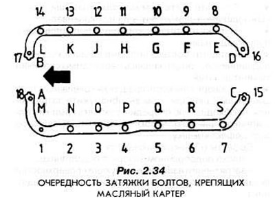
Install the oil pan and tighten its mounting bolts in three stages. Tighten according to Fig. 2.34:
- Stage I - in alphabetical order
- Stage II - in numerical order
- Stage III - in alphabetical order
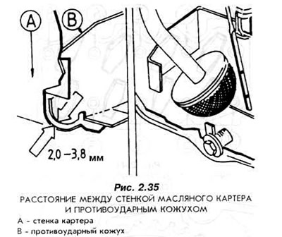
Note: Before installing the oil pan, check whether the distance shown in Fig. 2.35 between the wall of the oil pan and its shockproof casing is maintained (this distance should not be too large or too small). A bent oil pan must be replaced, since the dimensions shown in Fig. 2.35 ensure proper lubrication of the engine.
Install the oil pump.
Install the DIS ignition coil.
Screw on the oil filter with a well-lubricated gasket and tighten it by hand.
In a carburetor engine, install a fuel pump.
Install the water pump.
Degrease the seating surfaces of the cylinder head and engine housing under the cylinder head gasket.
Place the cylinder head gasket on the plane of the engine housing and put the cylinder head on. Tighten the new bolts securing the cylinder head in the order shown in Fig. 2.36.
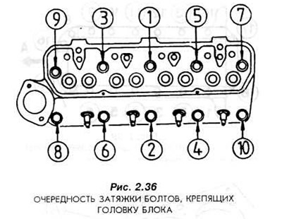
Tighten the bolts as follows:
- Stage I: 30 Nm
- Step II: Turn the bolts 90°
- Stage III: Turn the bolts another 90°
Insert the push rods, lubricated with oil.
Insert the axle with valve levers.
Connect the levers to the push rods.
Secure the valve lever shaft.
Install the thermostat in the head and mount the fitting with a new gasket.
Install the water pump belt pulley.
Adjust the valve clearance.
The clearance of the intake valve is 0.20-0.35 mm. The exhaust valve is 0.30-0.35 mm. The valve clearances must be adjusted according to the cylinder order given below.
| Divergent valves | Adjustable valves |
| IV cylinder | I cylinder |
| III cylinder | II cylinder |
| I cylinder | IV cylinder |
| II cylinder | III cylinder |
Install the cylinder head cover and tighten its mounting bolts.
Screw in the spark plugs.
Install high voltage wires.
Install the intake and exhaust manifolds.
Install the air filter.
For more information, please visit the website Fordbook.ru