DOHC Engine Crankshaft Main Bearing Designations
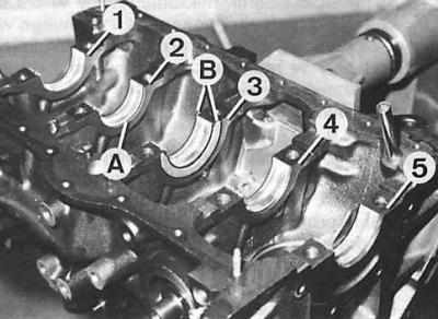
1–5 – bearing numbers, A – main bearing shell, B – crankshaft thrust half rings
DOHC Engine Connecting Rod Cap Designation
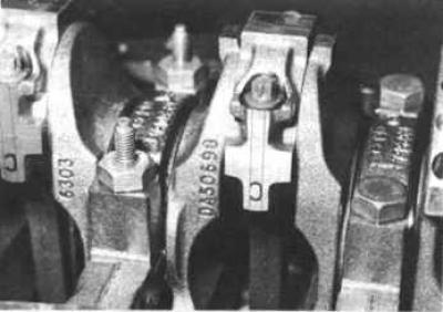
The top figure shows the complete set with a connecting rod.
The figure below shows the correct position of the cover relative to the connecting rod.
1. Insert dry main bearing shells into the sockets in the cylinder block.
2. Lubricate the working surfaces of the half-liners with oil and install the crankshaft on them.
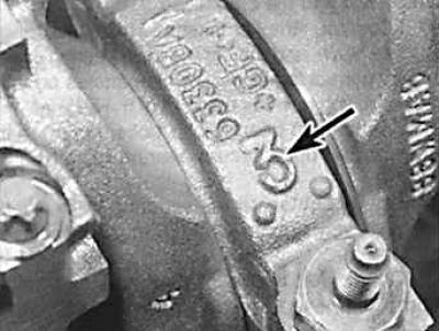
3. Install the main bearing caps together with the oiled half-liners; the arrows on the main bearing caps must point towards the camshaft drive (the arrow shows the marking on the main caps).
4. Tighten the main bearing cap bolts to the specified torque.
5. Using a set of feeler gauges, measure the axial clearance of the crankshaft. The feeler gauge is installed between the crankshaft journal and the thrust washers. The clearance should be within the values specified in subsection 3.2.1. To adjust the gap, you can install thrust washers of different thicknesses.
6. Turn the crankshaft to check if it is sticking. If the shaft is very difficult to turn or is sticking, it is necessary to disassemble and thoroughly check it.
7. Lubricate the cylinders and pistons with oil, with piston rings installed correctly.
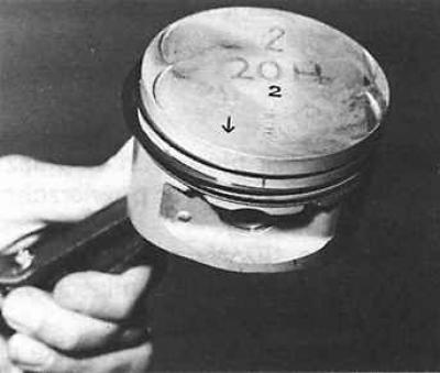
8. Install the piston-connecting rod units in the cylinders, compressing the piston rings with a special device. Point the arrows on the pistons toward the valve timing drive (towards the front of the engine).
9. Install the connecting rod bearings and connecting rod caps, tightening the bolts to the specified torque.
10. Check the axial clearance of the connecting rods on the crank pins.
11. Install the clutch shaft bearing into the hole in the rear of the crankshaft.
12. Remove the old rear crankshaft sealing ring from the cover. Install the cover on the cylinder block. Lubricate the working edges of the new sealing ring with fresh engine oil and insert it into the cover using a suitable tubular mandrel with the working edges facing inward.
13. Install the front cylinder block cover.
14. Install the oil deflector and oil pickup tube with a new gasket.
15. Install a new gasket into the oil pan grooves.
16. Apply sealant to the areas that meet the sealing ring cover.
17. Install the oil pan.
18. Install the flywheel on the crankshaft, tightening the flywheel mounting bolts (lubricate the threads with oil) to the appropriate torque.
19. Using the tool, center the clutch disc on the flywheel and install the clutch master cylinder.
20. Install the crankshaft position sensor and oil pressure sensor.
21. Install the oil pump in place and tighten the mounting bolts to the appropriate torque.
22. Install the oil filter and water pump.
23. Install a new gasket on the cylinder block.
24. Turn the crankshaft so that the pistons are in the middle of their stroke.
25. Install the cylinder head onto the cylinder block.
26. Lubricate the threads of the cylinder head mounting bolts with a thin layer of engine oil, install them in place and tighten to the required torque in a specific sequence (see subsection 3.2.1).
27. Lubricate the camshaft bearings in the head with a thin layer of engine oil and install the camshafts in place.
28. Lubricate the camshaft bearing caps with a thin layer of engine oil and install them in place in accordance with the marking. The bearing caps of the camshaft controlling the intake valves are marked R1–R5, and the bearing caps of the camshaft controlling the exhaust valves are marked L1–L5. The numbering of the caps is from the drive side of the valve timing mechanism.
29. Install the oil supply line to the camshaft cams.
30. Gradually and consistently tighten the camshaft cap mounting nuts in a specific sequence. Tighten the mounting nuts by hand, turning them sequentially by 180° until the cover touches the cylinder head. Tightening sequence: L1 and R1, L5 and R5, L3 and R3. Then tighten the remaining cap mounting nuts by hand.
31. Tighten the cover mounting nuts to the required torque, turning them by the same angle in the following sequence: L1 and R1, L5 and R5, L3 and R3, L2 and L4, R2 and R4.
32. Check that the crankshaft is in the position corresponding to the installation of the piston of cylinder 1 at the top dead center in the compression stroke, while the keyway should be directed downwards.
Please note: The timing chain contains copper elements that are used to correctly position the timing mechanism when installing the chain.
33. Lower the chain from the top into the casing, with the single copper link of the chain at the bottom.
34. Insert the key into the crankshaft groove.
35. Install the chain onto the inner (large) sprocket, aligning the copper link of the chain with the mark on the sprocket.
36. Install the sprocket on the crankshaft, aligning the groove on the sprocket with the key, while the mark on the sprocket should be strictly at the bottom.
37. Insert the lower chain guide into place from above and screw it on with bolts whose threads are coated with a material that prevents the bolts from loosening.
38. Install the hydraulic chain tensioner plunger.
39. Install the chain tensioner lever, tensioner lever shaft and secure it with a lock washer.
40. Check and, if necessary, reset the camshafts. The camshafts must be in a position corresponding to the installation of the piston of cylinder 1 at the top dead center in the compression stroke, and the installation protrusions for the sprockets must be in line with the upper edge of the cylinder head and directed outward.
41. Install the chain onto the exhaust camshaft sprocket, aligning the mark on the sprocket with the middle of the section of chain between the copper links of the chain.
42. Install the sprocket on the camshaft. The mark on the sprocket should be in line with the top edge of the cylinder head and facing outward. Screw in the sprocket mounting bolt.
43. Install the chain onto the intake camshaft sprocket, aligning the mark on the sprocket with the middle of the section of chain between the copper links of the chain.
44. Install the sprocket onto the camshaft. The mark on the sprocket should be in line with the top edge of the cylinder head and facing outward.
45. Install the distributor drive gear onto the right camshaft.
46. Install the upper timing chain guide.
47. Turn the crankshaft several revolutions in the direction of engine operating rotation.
48. Check the position of the hydraulic tappet plunger.
49. Turn the crankshaft two revolutions in the direction of engine operating rotation and check the marks on the camshaft sprockets, which should be in line with the upper edge of the cylinder head and facing outward.
50. Turn the crankshaft one revolution in the direction of engine rotation and check the marks on the camshaft sprockets, which should be in line with the upper edge of the cylinder head and facing each other.
51. Install the oil pump drive chain onto the crankshaft sprocket, then install the drive sprocket and chain onto the oil pump.
52. Install the oil pump chain tensioner.
53. Check the condition of the sealing ring in the upper timing cover. If necessary, remove the old sealing ring and, using a tubular mandrel, install a new ring with the working edges toward the engine.
54. Install the upper timing cover with a new gasket.
55. Install the cylinder head cover.
56. Check the condition of the sealing ring in the lower timing cover. If necessary, remove the old sealing ring and, using a tubular mandrel, install a new ring with the working edges facing the engine.
57. Install the lower timing cover with a new gasket, without tightening the mounting bolts.
58. Install the auxiliary belt pulley onto the crankshaft and secure it with the old bolt, while centering the lower timing cover and finally tightening the cover mounting bolts.
59. Unscrew the old bolt from the pulley and screw in a new one, tightening it to the required torque.
60. Install the auxiliary belt tensioner mechanism, making sure that the protrusion on the rear of the tensioner mechanism fits into the corresponding hole in the engine cylinder block.
61. Install spark plugs, distributor and spark plug wires.
62. Install the generator, put on the drive belt and adjust its tension.
63. Fill the engine with motor oil.