O-rings and gaskets for DOHC engine
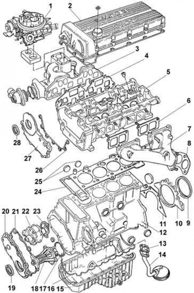
1 - carburetor, 2 - cylinder head cover, 3 - intake manifold, 4 - intake manifold gasket, 5 - cylinder head, 6 - exhaust manifold gasket, 7 - exhaust manifold, 8 - exhaust pipe gasket, 9 - rear seal crankshaft ring, 10 - crankshaft rear seal ring cover, 11 - gasket, 12 - cylinder block, 13 - oil receiver pipe gasket, 14 - oil receiver, 15 - oil pan, 16 - oil pan gasket, 17 - water pump seal ring, 18 - water pump, 19 - front crankshaft sealing ring, 20 - front cylinder cover, 21 - gasket, 22 - oil pump, 23 - gasket, 24 - cylinder head gasket, 25 - technological plug, 26 - gasket, 27 - front head cover, 28 - camshaft sealing ring
Removing the DOHC engine oil pump
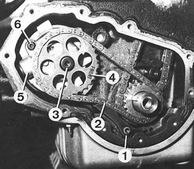
1 - chain tensioner, 2 - pump drive chain, 3 - pump sprocket bolt, 4 - pump sprocket, 5 - oil pump, 6 - oil pump bolt to cylinder block
Crank mechanism
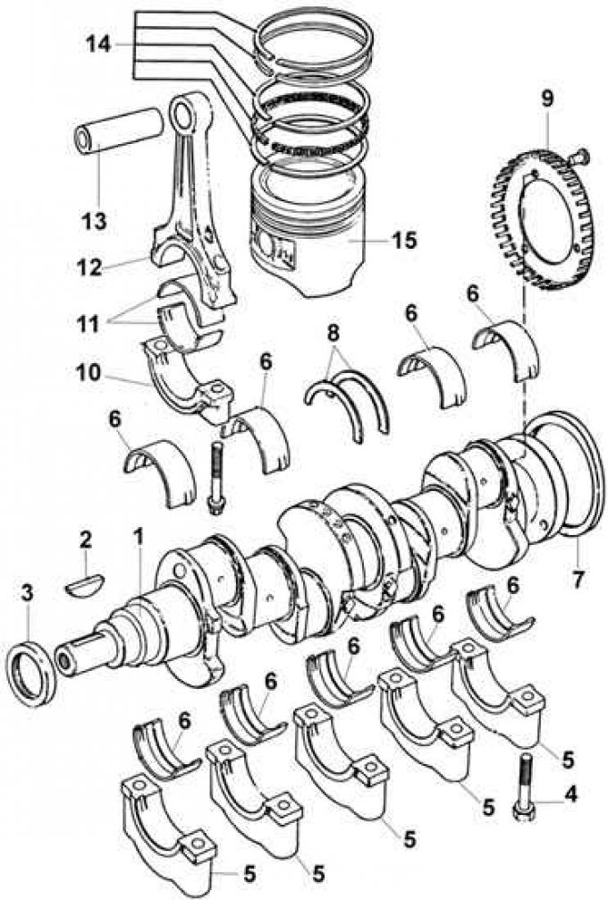
1 - crankshaft, 2 - segment key, 3 - front crankshaft sealing ring, 4 - crankshaft main bearing cap bolt, 5 - crankshaft main cover, 6 - main bearings, 7 - crankshaft rear sealing ring, 8 - thrust half rings, 9 - ring gear, 10 - connecting rod cover, 11 - connecting rod bearings, 12 - connecting rod, 13 - piston pin, 14 - piston rings, 15 - piston
If possible, install the engine on a stand; if not, install it in such a way that the engine cannot be damaged when unscrewing tightly tightened nuts and bolts.
Cleanliness is very important during disassembly to prevent contamination of the disassembled components. Before proceeding with disassembly, clean the outside of the engine with kerosene or, if heavily soiled with solvent.
When the parts are removed from the engine, wash them in kerosene. Never immerse parts with internal lubrication channels in kerosene, such parts should be thoroughly wiped with a cloth soaked in kerosene, and the lubrication channels should be cleaned with a wire rope.
1. Drain the engine oil from the engine and remove the oil level gauge.
2. Unscrew the oil filter.
3. Unscrew the bolts securing the clutch pressure plate housing to the flywheel and remove it.
4. Remove flywheel.
5. Remove the alternator drive belt.
6. Unscrew the long lower alternator mounting bolt, then the upper bolt and remove the alternator.
7. Unscrew the central bolt securing the drive belt tensioner and remove the tensioner.
8. Remove the cylinder head cover.
9. Remove the ignition distributor.
10. Remove the top cover of the gas distribution mechanism.
11. Rotate the crankshaft in the direction of operating rotation until it reaches top dead center on the compression stroke of cylinder 1.
12. Loosen the crankshaft pulley bolt. To avoid turning the crankshaft when unscrewing the pulley, it is necessary to fix the flywheel by the teeth of the ring gear.
13. Partially unscrew the bolt securing the crankshaft pulley, and using a puller, remove the pulley. The grips of the puller must rest against the metal part of the pulley.
14. Unscrew the central bolt securing the drive belt tensioner and remove the tensioner.
15. Unscrew the 11 mounting bolts and remove the bottom cover of the gas distribution mechanism. Remove rubber seal.
16. Unscrew the bolt and remove the oil pump drive chain tensioner.
17. Unscrew the sprocket mounting bolt on the oil pump and remove the sprocket together with the chain.
18. Remove the upper chain guide.
19. Unscrew the two bolts securing the lower chain guide and remove it upwards.
20. Remove the retaining ring from the axle of the timing chain tensioner lever and remove the tensioner lever.
21. Remove the axle of the timing chain tensioner lever using the M6x70 bolt and bushing.
22. Mark the camshaft sprockets and remove them.
23. Remove the sprocket and key from the crankshaft.
24. Pull the timing chain up.
Attention! To avoid collision between pistons and valves, do not rotate the engine crankshaft when the timing chain is removed.
25. Remove chain tensioner.
26. Remove the chain tensioner hydraulic pusher.
27. Unscrew the nuts and remove the camshaft mounting covers together with the oil supply pipe. The camshaft covers are marked for future reinstallation. In the absence of marking, before removing the covers, they must be marked.
28. Remove camshafts from cylinder head. There is a green mark on the camshaft that controls the exhaust valves. If there is no mark, mark the camshafts.
29. Remove the hydraulic valve lifters and place them in the appropriate oil containers for later reinstallation.
30. Unscrew the 13 cylinder head bolts gradually and sequentially in reverse order to tightening.
Attention! Reusing the cylinder head bolts is not recommended.
31. Remove the cylinder head and set it on two wooden blocks to avoid damaging the valves.
32. Remove the cylinder head gasket and guide bushings.
33. Unscrew the 4 bolts and remove the oil pump from the cylinder block.
34. Remove the oil pressure sensor and crankshaft position sensor.
35. Unscrew the bolts and nuts securing the oil sump and remove it.
36. Turn over the engine.
37. Remove the oil pickup tube and oil deflector.
38. Remove rear crankshaft cover with O-ring.
39. Check the presence of markings on the caps of the main and connecting rod bearings of the crankshaft. If they are not available, mark the bearings with a center punch or indelible pencil.
40. Unscrew the connecting rod bolts, remove their covers, remove the connecting rod bearings and remove the pistons together with the connecting rods from the cylinders.
41. Unscrew the bolts of the main bearing caps, remove the main bearing caps and remove the liners.
42. Remove crankshaft from cylinder block.
43. Remove the crankshaft thrust washers.
Visitor comments