Electrical diagram of the EEC IV system of the DOHC 2.0 dm³ engine
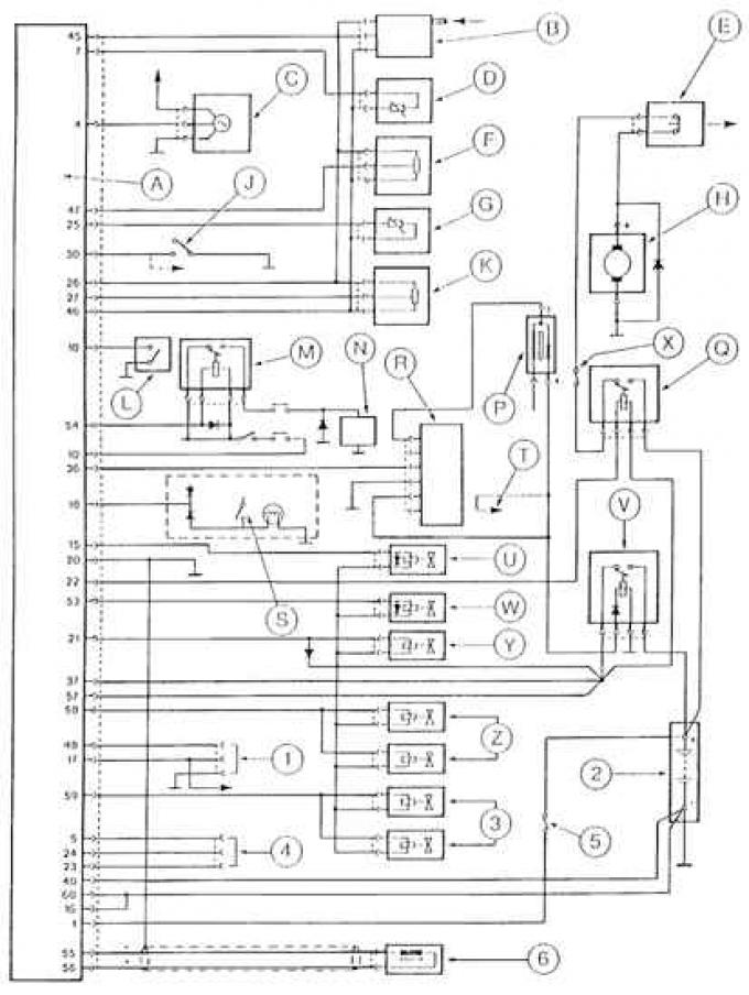
A – Electronic control device EEC IV; B – absolute pressure sensor; C – speed sensor; E – inertial switch; F – throttle position sensor; G – incoming air temperature sensor; H – Electric fuel pump; J – Automatic transmission gear shift lever neutral position sensor; K – potentiometer for adjusting CO content; L – injector manifold thermal switch; M – air conditioning switch relay; N – air conditioning activation rod; P – ignition coil; Q – fuel pump relay; R – TFI IV ignition booster module; S – brake pedal position sensor; T – connection to ignition switch; U – electromagnet for switching 3rd and 4th gears of the automatic transmission gear shift lever; V – fuel injector power supply relay; W – automatic transmission clutch control release solenoid; X – fuel pump fuse; Y – idle speed control valve solenoid; Z – fuel injectors N1 and 2;
1 – diagnostic connector; 2 – battery; 3 – fuel injectors N 3 and 4; 4 – service connector; 5 – Electronic control unit memory fuse EEC IV; 6 – crankshaft position sensor.
The text is available on the specified website info portal fordbook