Contents: Design and operation of the ignition… ↳ Ignition system ESC II ↳ Ignition system EEC IV ↳ Removal and installation the… ↳ Checking the ignition system… ↳
Design and operation of the ignition system
Both types of DOHC engines are equipped with an electronic ignition system:
- engines with carburetor fuel system: ignition system ESC II;
- injection engines: ignition system EEC IV.
Ignition system ESC II
Electrical diagram of the electronic ignition system ESC II of the carburetor engine DOHC 2.0 dm³
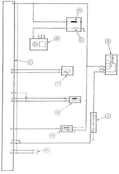
A – electromagnetic valve for shutting off fuel supply after engine is switched off, B – generator, C – resistor heating element of automatic starting device of carburetor, D – ignition switch, E – ignition control module ESC II, F – coolant temperature sensor, G – crankshaft position and speed sensor, H – ignition coil, J – battery, K – fuel octane coding connector
This system contains:
- ignition distributor with high voltage distributor and contactless Hall sensor acting as engine crankshaft speed sensor;
- ignition coil;
- vacuum sensor in the intake manifold;
- coolant temperature sensor;
- automatic transmission neutral position sensor (only in vehicles with automatic transmission).
The electronic ignition control module ESC II receives signals from these sensors and, based on them and the data contained in its memory, selects the optimal, for the given engine operating conditions, moment of interruption of the current in the primary winding of the ignition coil, and thus the optimal ignition advance angle. Then it switches on the current in the primary winding and interrupts the current in it at the moment when ignition should occur in the next cylinder, again supplies current to this winding, etc.
The ignition timing angle is constantly adjusted in accordance with the signals received and the data contained in the memory of the electronic module.
In engines with a carburetor, the ESC II ignition control module also adjusts the throttle valve position during idle speed depending on the engine speed, engine load (e.g. engaging a gear in an automatic transmission or switching on the air conditioning compressor), engine thermal state, and the throttle valve position.
Checking the ignition system components ESC II
| The element being tested | Measuring between contacts | Ignition | Meaning | Notes |
| Connection of the crankcase to the ground | "16" and mass "3" and mass | Off | 0 – 0.5 Ohm | |
| Fuel octane number corrector | "7" and "16" "19" and "16" | Off | The resistance is infinitely large | Before testing, disconnect the ESC II module |
| Coolant temperature sensor | "10" and "22" | Off | 37 kOhm at 20°C 4 kOhm at 80°C | |
| Throttle Lever Damper Solenoid Valve | "24" and "4" | Off On | Resistance is infinitely large 65 – 80 Ohm | If there is |
| Crankshaft position sensor | "5" and "18" "17" and "16" | Included | 300 – 500 Ohm Resistance is infinitely large | |
| Power supply for the ESC II module | "4" and "16" | Included | 10 – 14 V |
Caution! The method for checking the ignition system components of a DOHC engine combined with a fuel injection system included in the EEC IV engine management system is given in the fuel injection section.
Ignition system EEC IV
This ignition system operates on the same principle as the ESC II ignition system, only it is combined with fuel injection into the overall EEC IV engine management system, and the electronic control unit also controls the injection system.
Attention! The described ignition systems do not require adjustment.
Removal and installation the ignition distributor
Removing and installing the ignition distributor is not very difficult. The elements of the DOHC engine ignition system are shown in the figure.
DOHC Engine Ignition System Components
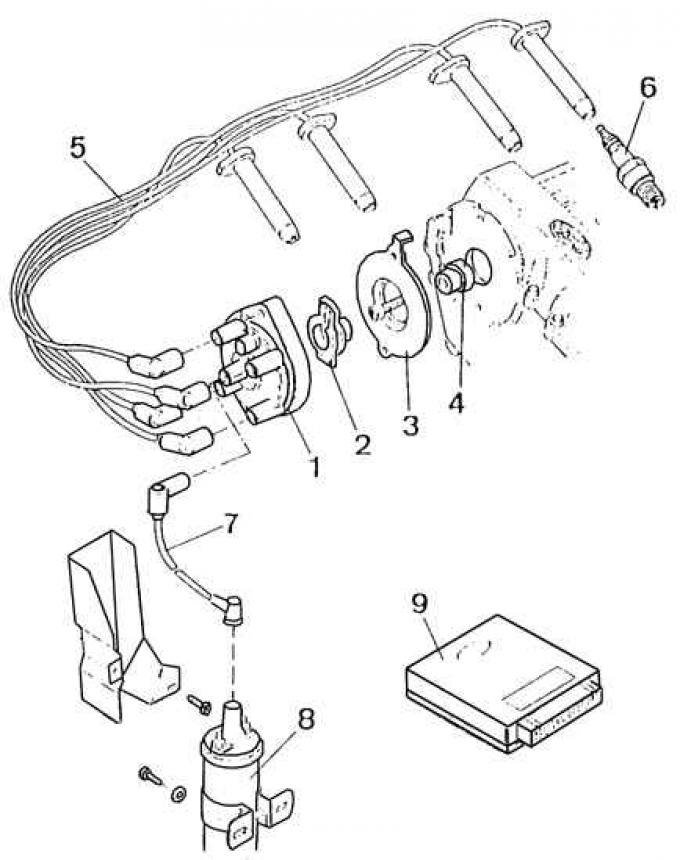
1 – distributor cap, 2 – distributor rotor, 3 – plate, 4 – driver, 5 – spark plug high-tension wires, 6 – spark plug, 7 – ignition coil high-tension wire, 8 – ignition coil, 9 – electronic ignition control module
The ignition distributor can only be installed in one, correct position.
Checking the ignition system components
For a DOHC carbureted engine, disconnect the ESC II ignition control module multi-pin connector and measure the resistance and voltage at the selected connector pins using a multimeter according to the table below.
In case of incorrect values of electrical parameters, before considering the given element as damaged, the condition of the corresponding electrical circuit should be checked.