Vehicle wiring diagrams Ford Focus 2
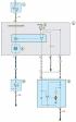
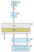
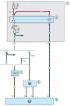
Scheme 1. Wiper and windshield washer connections
1 - switch (lock) ignition; 2 - mounting block of relays and fuses; 3 - fuse 15 A; 4 - windshield wiper relay; 5 - windshield washer motor; 6 - combined steering column...
1 - switch (lock) ignition; 2 - mounting block of relays and fuses; 3 - fuse 15 A; 4 - windshield wiper relay; 5 - windshield washer motor; 6 - combined steering column...

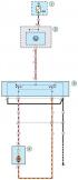
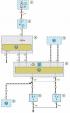
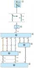
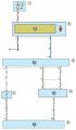
Diagram 2. Battery Charging System Connections
1 - electronic transmission control unit; 2 - fuse mounting block; 3 - fuse 10 A; 4 - fuse 15 A; 5 - battery; 6 - starter; 7 - generator
There are 1 a comment
1 - electronic transmission control unit; 2 - fuse mounting block; 3 - fuse 10 A; 4 - fuse 15 A; 5 - battery; 6 - starter; 7 - generator
There are 1 a comment
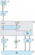
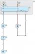
Scheme 3. Connections of the hydraulic drive system of the brake system
1 - fuse mounting block; 2 - mounting block of fuses and relays; 3 - adjustable brake pedal switch; 4 - brake pedal motor
1 - fuse mounting block; 2 - mounting block of fuses and relays; 3 - adjustable brake pedal switch; 4 - brake pedal motor
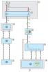
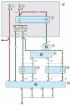
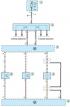
Diagram 4. Connections of the ventilation, heating and air conditioning system
1, 9 - mounting block of fuses and relays; 2 - fuse 30 A; 3 - heater electric fan relay; 4 - heater electric fan motor; 5 - heater electric fan resistor; 6 - switch of...
1, 9 - mounting block of fuses and relays; 2 - fuse 30 A; 3 - heater electric fan relay; 4 - heater electric fan motor; 5 - heater electric fan resistor; 6 - switch of...
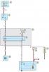
Diagram 5. Connections of the engine start system
1, 5 - fuse 20 A; 2, 4 - mounting block of fuses and relays; 3 - switch (lock) ignition; 6 - starter relay; 7 - battery; 8 - fusible insert 150 A; 9 - starter; 10 -...
1, 5 - fuse 20 A; 2, 4 - mounting block of fuses and relays; 3 - switch (lock) ignition; 6 - starter relay; 7 - battery; 8 - fusible insert 150 A; 9 - starter; 10 -...
Scheme 6a. Speed Control Connections
1 - fuse 20 A; 2 - fuse mounting block; 3 - switch (lock) ignition; 4 - mounting block of fuses and relays; 5 - sensor; 6 - speed switch
1 - fuse 20 A; 2 - fuse mounting block; 3 - switch (lock) ignition; 4 - mounting block of fuses and relays; 5 - sensor; 6 - speed switch
Scheme 6b. Speed Control Connections
1 - fuse mounting block; 2 - fuse 20 A; 3 - switch (lock) ignition; 4 - mounting block of fuses and relays; 5 - electronic engine and transmission control unit; 6 -...
1 - fuse mounting block; 2 - fuse 20 A; 3 - switch (lock) ignition; 4 - mounting block of fuses and relays; 5 - electronic engine and transmission control unit; 6 -...
Scheme 7a. Engine management connections
1 - fuse 3 A; 2 - fuse 20 A; 3 - relay; 4 - mounting block of fuses and relays; 5, 6 - fuse 10 A; 7, 8, 10 - electronic engine and transmission control unit; 9 -...
1 - fuse 3 A; 2 - fuse 20 A; 3 - relay; 4 - mounting block of fuses and relays; 5, 6 - fuse 10 A; 7, 8, 10 - electronic engine and transmission control unit; 9 -...
Scheme 7b. Engine management connections
1 - fuse mounting block; 2 - fuse 20 A; 3 - switch (lock) ignition; 4 - mounting block of fuses and relays; 5 - fuse 15 A; 6 - fuel pump relay; 7 - diagnostic connector;...
1 - fuse mounting block; 2 - fuse 20 A; 3 - switch (lock) ignition; 4 - mounting block of fuses and relays; 5 - fuse 15 A; 6 - fuel pump relay; 7 - diagnostic connector;...
Scheme 7c. Engine management connections
1 - mounting block of fuses and relays; 2 - fuse 20 A; 3 - main relay of the engine control system; 4 - fuse 10 A; 5 - electronic engine and transmission control unit; 6...
1 - mounting block of fuses and relays; 2 - fuse 20 A; 3 - main relay of the engine control system; 4 - fuse 10 A; 5 - electronic engine and transmission control unit; 6...
Scheme 7d. Engine management connections
1 - fuse mounting block; 2 - fuse 10 A; 3 - pressure sensor in the power steering system; 4, 6 - electronic transmission control unit; 5 - incoming air temperature...
1 - fuse mounting block; 2 - fuse 10 A; 3 - pressure sensor in the power steering system; 4, 6 - electronic transmission control unit; 5 - incoming air temperature...

Scheme 7d. Engine management connections
1 - fuse mounting block; 2 - fuse 20 A; 3 - switch (lock) ignition; 4 - mounting block of fuses and relays; 5 - fuse 10 A; 6 - accelerator pedal position sensor; 7 -...
1 - fuse mounting block; 2 - fuse 20 A; 3 - switch (lock) ignition; 4 - mounting block of fuses and relays; 5 - fuse 10 A; 6 - accelerator pedal position sensor; 7 -...

Scheme 7e. Engine management connections
1, 3 - electronic engine and transmission control unit; 2 - coolant temperature sensor; 4 - knock sensor; 5 - crankshaft position sensor; 6 - camshaft position sensor
1, 3 - electronic engine and transmission control unit; 2 - coolant temperature sensor; 4 - knock sensor; 5 - crankshaft position sensor; 6 - camshaft position sensor
Scheme 7g. Engine management connections
1 - fuse mounting block; 2 - fuse 10 A; 3 - ignition coil module; 4, 6 - electronic engine and transmission control unit; 5 - knock sensor; 7 - crankshaft position...
1 - fuse mounting block; 2 - fuse 10 A; 3 - ignition coil module; 4, 6 - electronic engine and transmission control unit; 5 - knock sensor; 7 - crankshaft position...
Scheme 8a. Air conditioning connections
1 - fuse 10 A; 2 - fuse 30 A; 3 - mounting block of fuses and relays; 4 - electric fan relay; 5 - electric fan; 6, 8 - electronic engine and transmission control unit; 7...
1 - fuse 10 A; 2 - fuse 30 A; 3 - mounting block of fuses and relays; 4 - electric fan relay; 5 - electric fan; 6, 8 - electronic engine and transmission control unit; 7...
Scheme 8b. Air conditioning connections
1 - fuse mounting block; 2 - fuse 50 A; 3 - block of electric fans of the cooling system; 4, 6 - electronic engine and transmission control unit; 5 - switch of the air...
1 - fuse mounting block; 2 - fuse 50 A; 3 - block of electric fans of the cooling system; 4, 6 - electronic engine and transmission control unit; 5 - switch of the air...

Diagram 9 Power Steering System Connections
1 - fuse 80 A; 2 - fuse 10 A; 3 - fuse mounting block; 4 - instrument cluster; 5 - electric power steering module; 6 - steering column shaft position sensor
1 - fuse 80 A; 2 - fuse 10 A; 3 - fuse mounting block; 4 - instrument cluster; 5 - electric power steering module; 6 - steering column shaft position sensor

Scheme 10a. Anti-Lock Braking System (ABS) Connections
1 - fuse 20 A; 2 - fuse 30 A; 3 - fuse 10 A; 4 - fuse mounting block; 5 - fuse 15 A; 6, 8 - mounting block of fuses and relays; 7 - stop lamp switch; 9 - electronic...
1 - fuse 20 A; 2 - fuse 30 A; 3 - fuse 10 A; 4 - fuse mounting block; 5 - fuse 15 A; 6, 8 - mounting block of fuses and relays; 7 - stop lamp switch; 9 - electronic...

Scheme 10b. Anti-Lock Braking System (ABS) Connections
1 - electronic block of the anti-lock braking system; 2 - right front wheel speed sensor; 3 - right rear wheel speed sensor; 4 - left front wheel rotation speed sensor;...
1 - electronic block of the anti-lock braking system; 2 - right front wheel speed sensor; 3 - right rear wheel speed sensor; 4 - left front wheel rotation speed sensor;...

Scheme 11. Connections of the dynamic stabilization system of the car
1, 3 - electronic module of the dynamic stabilization system; 2 - angular velocity sensor; 4 - steering wheel position sensor
1, 3 - electronic module of the dynamic stabilization system; 2 - angular velocity sensor; 4 - steering wheel position sensor
This section is available on russian, bulgarian, belarusian, ukrainian, serbian, croatian, romanian, polish, slovak, hungarian
See other similar sections for Ford cars:
• Electrical equipment: Schematic diagrams Ford Mondeo 3 (2000-2007)
• Electrical equipment: Schematic diagrams Ford Escort 5 (1990-1997)
• Electrical equipment: Schematic diagrams Ford Mondeo 3 (2000-2007)
• Electrical equipment: Schematic diagrams Ford Escort 5 (1990-1997)
Focus 2
Focus Turnier 1
Focus 1
- General information
- Vehicle device
- Owner's manual
- Faults en route
- Maintenance
- First maintenance
- Second maintenance
- Applications
- Consumables and spare parts
- Auto mechanic tips
- Power unit
- Engine repair
- Engine seal parts
- Cooling system
- Exhaust system
- Supply system
- Clutch
- Car gearbox
- Front wheel drives
- Chassis
- Front suspension
- Rear suspension
- Steering
- Brake system
- Wheels and tires
- Body and coating
- Body elements
- Side doors
- Tailgate
- Salon elements
- Safety system
- Windshield wipers and washers
- Body Care
- Electrical equipment
- Instruments and motors
- Battery and alternator
- Egnition lock
- Engine management
- Headlights and lighting
- Switches and sensors
- Schematic diagrams
Focus Turnier 1
- General information
- Introduction to guide
- Car care
- Power unit
- Engine repair
- Lubrication system
- Cooling system
- Fuel injection (gasoline)
- Fuel injection (diesel)
- Ignition system
- Power and exhaust system
- Transmission
- Clutch and drive shafts
- Mechanical gearbox
- Automatic gearbox
- Chassis
- Car suspension
- Steering
- Wheels and tires
- Brake system
- Body
- Exterior
- Interior
- Heating and ventilation
- Electrical equipment
- Equipment and devices
- Lighting and signaling
- Power devices
- Electrical circuits
Focus 1
- General information
- Using the manual
- Identification codes
- Power unit
- Engine
- Engine 1.4/1.6 Zetec-SE
- Engine 1.6/1.8/2.0 Zetec-E
- Engine Duratec ST 2.0 l
- Engine Duratec 8V 1.6 l
- Diesel engine 1.8 l
- Engine cooling
- Fuel supply
- Accessory drive
- Launch system
- Ignition system
- Air and vapor
- Engine management
- Exhaust toxicity
- Exhaust system
- Automatic gearbox
- Clutch
- Mechanical gearbox iB5
- Mechanical gearbox MTX-75
- Mechanical gearbox MT285
- Chassis
- Front suspension
- Rear suspension
- Wheels and tires
- Front axle axles
- Brake system
- Hydraulic brake
- Anti-lock braking system
- Steering
- Body and coating
- Body panels
- Body elements
- Salon elements
- Glass, frames and mechanisms
- Windshield wipers and washers
- Car sunroof
- Seat belts
- Body repairs
- Back elements
- Electrical equipment
- Climate control
- Heating and ventilation
- Instruments and control lamps
- Battery and alternator
- Audio system
- Headlights and lighting
- Power distribution
- Electronic Function Group
FordBook.ru © 2014-2024 • Mobile version • Interesting to read • Sitemap: EN BG BY UA RS HR RO PL SK HU • Site search • Contact with administration
Focus 1 • Focus Turnier 1 • Focus 2 • Mondeo 1 • Mondeo 1 and 2 • Mondeo 2 • Mondeo 3 • Mondeo 4 • Escort 3 • Escort 4 • Escort 5 • Fiesta 2 • Fiesta 4 • Taurus 1 and 2 • Fusion • Scorpio 1 • Scorpio 2 • Sierra •
Focus 1 • Focus Turnier 1 • Focus 2 • Mondeo 1 • Mondeo 1 and 2 • Mondeo 2 • Mondeo 3 • Mondeo 4 • Escort 3 • Escort 4 • Escort 5 • Fiesta 2 • Fiesta 4 • Taurus 1 and 2 • Fusion • Scorpio 1 • Scorpio 2 • Sierra •