The control device in the system is an electronic control unit (ECU). Based on the information received from the sensors, the ECU calculates the parameters for fuel injection control and ignition timing control. In addition, in accordance with the embedded algorithm, the ECU controls the operation of the electric motor of the fan of the engine cooling system and the electromagnetic clutch for turning on the air conditioning compressor, performs the function of self-diagnostics of the system elements and notifies the driver of any malfunctions.
In the event of failure of individual sensors and actuators, the ECU includes emergency modes that ensure engine performance.
The amount of fuel supplied by the injectors is determined by the duration of the electrical signal from the ECU. The electronic unit monitors data on the state of the engine, calculates the need for fuel and determines the required duration of fuel supply by injectors (signal duration). To increase the amount of fuel supplied, the duration of the signal increases, and to reduce the fuel supply, it decreases.
The engine management system, along with the electronic control unit, includes sensors, actuators, connectors and fuses.
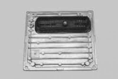
Electronic control unit (ECU) connected by electrical wires to all sensors of the system. Receiving information from them, the block performs calculations in accordance with the parameters and control algorithm stored in the memory of a programmable read-only memory device (PROM), and controls the executive devices of the system. The program variant recorded in the PROM memory is indicated by the number assigned to this ECU modification.
The control unit detects a malfunction, identifies and stores its code, even if the failure is unstable and disappears (e.g. due to poor contact). The signal lamp for a malfunction of the engine management system in the instrument cluster goes out 10 s after the failure of the unit is restored.
After repair, the fault code stored in the memory of the control unit must be erased. To do this, turn off the power supply of the unit for 10 s (remove the fuse for the power supply circuit of the electronic control unit or disconnect the wire from the terminal «minus» battery).
The unit supplies 5 and 12 V direct current to various sensors and switches of the control system. Since the electrical resistance of the power circuits is high, the test lamp connected to the system outputs does not light up. To determine the supply voltage at the computer terminals, a voltmeter with an internal resistance of at least 10 MΩ should be used.
The ECU is not repairable and should be replaced if it fails.
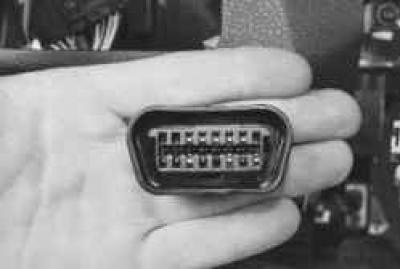
Diagnostic connector serves to display from the memory of the ECU fault codes detected during the operation of the engine management system.
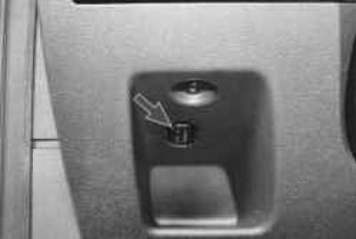
The diagnostic connector is located in the passenger compartment on the left side of the instrument panel above the shelf for small items. You can connect a scanning device to the diagnostic socket, which reads information from the serial data line.
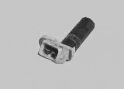
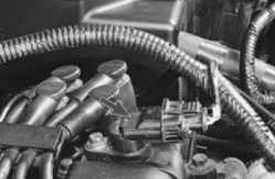
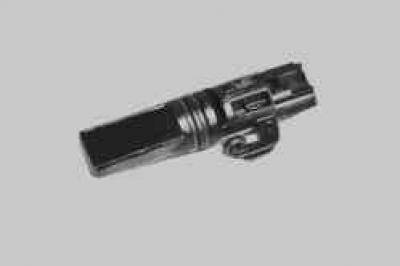
crankshaft position sensor inductive type is designed to synchronize the operation of the electronic control unit with the TDC of the pistons of the 1st and 4th cylinders and the angular position of the crankshaft.
The sensor is mounted at the rear of the engine opposite the master teeth on the flywheel. The master teeth are made on the surface of the flywheel at regular intervals. One tooth is missing to create a sync pulse («reference» momentum), which is necessary to coordinate the operation of the control unit with the TDC of the pistons in the 1st and 4th cylinders.
As the crankshaft rotates, the teeth change the sensor's magnetic field, inducing AC voltage pulses. The control unit determines the crankshaft speed from the sensor signals and sends pulses to the injectors.
If the sensor fails, the engine cannot be started.
Camshaft Position Sensors inductive type are used to organize phased fuel injection in accordance with the order of operation of the cylinders. The signals from the intake and exhaust camshaft sensors are also used by the controller to control the change in valve timing depending on the engine operating mode. If a malfunction occurs in the circuit of any of the sensors, the controller stores its code in its memory and turns on the signal lamp.
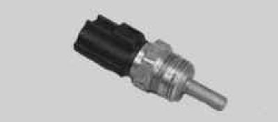
coolant temperature sensor installed in the engine cooling system. The sensing element of the sensor is a thermistor, the electrical resistance of which varies inversely with temperature. Low coolant temperature (-40°С) the resistance of the thermistor is about 100 kOhm, when the temperature rises to +130°C, it decreases to 70 Ohm.
The electronic unit feeds the temperature sensor circuit with a constant reference voltage. The sensor signal voltage is maximum on a cold engine and decreases as it warms up. Based on the voltage value, the electronic unit determines the engine temperature and takes it into account when calculating the injection and ignition control parameters. If the sensor fails or there are violations in its connection circuit, the ECU sets the fault code and remembers it.
In addition to the above, the sensor indirectly also serves as a sensor for the coolant temperature indicator in the instrument cluster. According to information from this sensor, the electronic engine control unit changes the readings of the pointer. To eliminate the problem, check the reliability of the contact connections in the wiring to the sensor or replace the sensor.
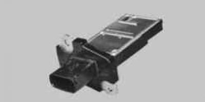
Combined mass flow and intake air temperature sensor. The principle of operation of the mass air flow sensor is based on maintaining a constant temperature of the resistors (the higher the airflow rate, the more current is needed to maintain the temperature of the resistor). The principle of operation of the intake air temperature sensor is similar to that of the coolant temperature sensor. Depending on the readings of these sensors, the ECU adjusts the amount of fuel injected into the cylinder to obtain the optimal working mixture.
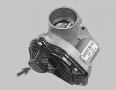
Throttle position sensor made in one piece with the cover of the throttle assembly.
The sensor is a potentiometer, one end of which is supplied with «plus» supply voltage (5 V), and the other end is connected to «weight».
From the third output of the potentiometer (from the slider) is the output signal to the electronic control unit.
When the throttle is turned (from impact on the control pedal), the voltage at the output of the sensor changes. When the throttle is closed, it is lower than 0.5 V. When the throttle opens, the voltage at the sensor output rises, when the throttle is fully open, it should be more than 4 V.
By monitoring the output voltage of the sensor, the controller adjusts the fuel supply depending on the throttle opening angle (those. at the request of the driver).
The throttle position sensor does not require adjustment, as the control unit perceives idling (those. full throttle closing) as a zero point.
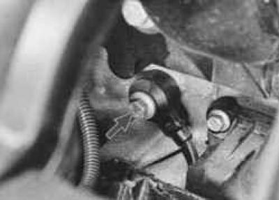
Vehicle speed sensor installed on the gearbox. The principle of operation of the sensor is based on the Hall effect. The sensor outputs rectangular voltage pulses to the electronic control unit with a frequency proportional to the speed of rotation of the drive wheels.
Oxygen concentration sensors (lambda probes) screwed into the threaded holes of the collector. Four oxygen concentration sensors are installed on Ford Focus II vehicles: two sensors for controlling the composition of the air-fuel mixture (at the entrance to the neutralizers) and two more - to evaluate the efficiency of the neutralizers (at the exit). A galvanic cell is located in the metal bulb of the sensor, washed by the flow of exhaust gases. Depending on the oxygen content in the exhaust gases, as a result of the combustion of the air-fuel mixture, the voltage of the sensor signal changes.
Information from each sensor enters the control unit in the form of low signals (from 0.1 V) and high (up to 0.9 V) level. With a low level signal, the control unit receives information about the high oxygen content. A high level signal indicates a low oxygen content in the exhaust gases.
Constantly monitoring the voltage of the sensor signal, the control unit adjusts the amount of fuel injected by the injectors. When the signal level of the sensors at the input to the converter is low (lean air-fuel mixture) the amount of fuel supplied increases, with a high signal level (rich mixture) - decreases. If the difference between the levels of the sensor signals at the input and output of the converter is less than the values admissible in this mode of operation, the control unit identifies a malfunction of the collector.
knock sensors (2 pcs.) attached to the top of the cylinder block in the areas between the 1st and 2nd, as well as between the 3rd and 4th cylinders and trap abnormal vibrations (detonation strikes) in the engine.
The sensing element of the knock sensor is a piezoelectric plate. During detonation, voltage pulses are generated at the output of the sensor, which increase with increasing intensity of detonation impacts. The controller, based on a sensor signal, regulates the ignition timing to eliminate detonation fuel flashes.
WARNING: 1. Before removing any components of the fuel injection control system, disconnect the wire from the terminal «minus» battery.
WARNING: 2. Do not start the engine if the cable lugs on the battery are loose.
WARNING: 3. Never disconnect the battery from the car's electrical system while the engine is running.
WARNING: 4. When charging the battery, disconnect it from the car's on-board network.
WARNING: 5. Do not expose the ECU to temperatures above 65°C in working condition and above 80°C in non-working condition (e.g. in a drying chamber). It is necessary to remove the computer from the car if this temperature is exceeded.
WARNING: 6. Do not disconnect or connect wires to the computer while the ignition is on.
WARNING: 7. Before carrying out electric welding work on the vehicle, disconnect the wires from the battery and the wiring harness pads from the computer.
WARNING: 8. Make all voltage measurements with a digital voltmeter with an internal resistance of at least 10 MΩ.
WARNING: 9. The electronic components used in the fuel injection system are designed for very low voltage, so they can be easily damaged by electrostatic discharge. To prevent damage to the computer, do not touch its terminals with your hands.
WARNING: 10. To diagnose the engine management system in all cases, a special scanner is required, therefore, in case of system malfunctions, contact a specialized service.
Visitor comments