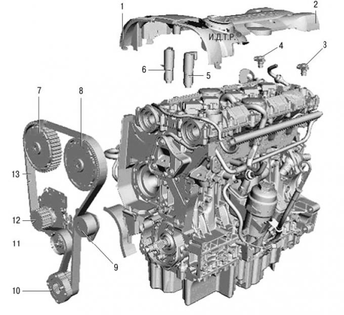
Pic. 5.39. Duratec-V15 engine with a volume of 2.5 liters with elements of the variable valve timing system: 1 - cover of the gas distribution mechanism drive; 2 – a cover of a head of the block of cylinders; 3 - intake camshaft position sensor; 4 - exhaust camshaft position sensor; 5 - solenoid valve for adjusting the position of the intake camshaft; 6 - solenoid valve for adjusting the position of the exhaust camshaft; 7 - mechanism for adjusting the position of the exhaust camshaft; 8 - mechanism for adjusting the position of the intake camshaft; 9 - intermediate pulley of the timing belt; 10 - toothed pulley of the timing belt on the crankshaft; 11 - timing belt tensioner; 12 - toothed pulley of the coolant pump; 13 - timing belt drive.
2.5L Duratec-V15 engine (pic. 5.39) - five-cylinder, 20-valve, displacement 2522 cm3, turbocharged and dual variable valve timing (VCT) with electronic control. By using a variable valve timing system for the intake and exhaust camshafts, maximum torque is achieved over a wide range of engine speeds.
The main elements of the engine are made of aluminum.
The cylinder head consists of two parts. Maintenance-free mechanical valve lifters are installed in the cylinder head. The upper section of the head of the block consists of a cover with integrated camshaft bearing caps. Spark plug wells are additionally sealed with rubber rings. A cover is installed above the spark plug wells to protect them from dirt and water.
The cylinder block consists of three parts.
This is the actual cylinder block, the lower section of the crankcase (main bearing frame) and oil sump. Five cast-iron cylinder liners are inserted into the cylinder block, which are not replaced during repairs.
The lower section of the crankcase acts as a reinforcing element. In addition, it serves as a housing for the lower main bearing shells.
An oil sump with developed fins serves as an additional reinforcing element.
A replaceable cylinder head gasket is installed between the block head and the cylinder block. Gaskets between other mating surfaces of the engine are hermetic-based seals.
The camshafts are mounted in six bearings, with the lower camshaft bearing shells located in the cylinder head, and the upper shells in the cylinder head cover.
Each camshaft has a solenoid hydraulic control valve for oil supply to the VCT system, which is controlled by an electronic engine control unit (ECU). The electronic unit receives information about the current crankshaft speed and engine load from the system sensors. Based on these input signals, a larger or smaller dynamic angle of rotation of the camshaft relative to the crankshaft is set using hydraulic valves.
The timing belt is tensioned automatically by a mechanical tensioner. The tension of the two V-ribbed accessory drive belts is also automatic.
The water pump is driven by the timing belt.
The crankshaft rotates in six main bearings. Thrust half rings of the crankshaft, which limit its axial movement, are installed in the fifth main bearing.
At the front end of the crankshaft, two toothed rims are made. The inner ring is used to drive the oil pump.
A pulley for the timing belt is installed on the outer spline crown.
NOTE: The timing belt pulley can only be slipped onto the shaft splines in one position. For this purpose, one spline in the hub hole of the timing belt pulley and one spline on the crankshaft are made wider than the others.
The pistons are made of aluminum alloy and have a graphite coating that serves to reduce friction and reduce noise. The pistons are cooled from below by jets of oil from oil nozzles screwed into the cylinder block.
The valve timing adjustment system has a hydromechanical drive.
Engine oil is supplied from the oil sump through the VCT oil control solenoid valves to the intake and exhaust camshaft control mechanisms in the amount necessary to change the dynamic position of the shafts in the mechanisms. The valve timing for the camshaft is set by the electronic control unit (ECU) engine with advance or delay, depending on the signals received by the sensors of the engine management system.
The VCT controls for both the intake and exhaust camshafts are self-set to the locked home position when the intake camshaft is locked by a special spring-loaded locking pin engaging the shaft.
The movement of the VCT mechanisms to the locked home position is provided by the tension force of the timing belt.
In the locked home position, the intake camshaft VCT control mechanism is in the "intake timing retard" position, and the exhaust camshaft VCT control unit is in the "exhaust timing advance" position.
When the engine is started, the lock is hydraulically released when a certain engine oil pressure is reached.
NOTE: The intake and exhaust camshaft VCT control mechanisms can only be replaced as a single unit during repair.
When starting the engine, engine oil is pumped from the oil sump by the oil pump, supplied to the camshaft oil channels through the oil channels in the cylinder block and engine head, and then sent from there to the oil control solenoid valve 7 (pic. 5.40) VCT and to the locking pin 2. The locking pin is retracted by oil pressure, resulting in a mechanical connection between the camshaft pulley 1 and the rotor 3.
When the VCT control mechanism is in lag mode, chamber b is filled with engine oil. Rotor 3 rotates clockwise, engine oil pressure in chamber b is greater than in chamber a. The engine oil returning from chamber a flows through the oil return port to the oil control solenoid valve VCT and from there returns to the oil sump.
When the VCT control mechanism is in advanced mode, chamber a is filled with engine oil. Rotor 3 turns counterclockwise, engine oil pressure in chamber a is greater than in chamber b. The engine oil returning from chamber b flows through the oil return port to the VCT oil control solenoid valve and from there returns to the oil sump.
When checking the valve timing, make sure that the alignment marks are exactly aligned (pic. 5.41).
When checking and adjusting the valve timing, the timing cover must always be installed. In addition, the timing belt must be correctly tensioned, since alignment marks are provided on its outer surface for the pulleys of both camshafts.
The mark on the timing belt pulley mounted on the crankshaft must exactly match the mark on the oil pump housing.
The timing belt tensioner mechanism includes a spring and a friction element. The latter serves to absorb small vibrations and fluctuations in the engine speed. The spring maintains the correct timing belt tension regardless of belt wear and engine temperature.
Timing belt tension should be adjusted when the engine is cold.
NOTE: If the engine temperature is higher or lower, be aware that the timing belt tensioner setting elements will assume a different position from their original position at 20°C (pic. 5.42).
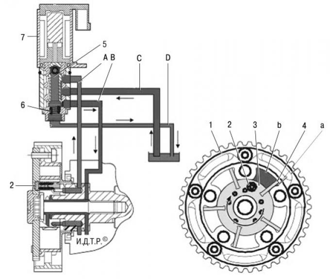
Pic. 5.40. Scheme of operation of the solenoid valve for controlling the oil supply: 1 - pulley for the mechanism for changing the valve timing; 2 - spring-loaded locking pin; 3 - rotor; 4 - rotor blade; 5 - plunger; 6 - return spring; 7 - solenoid valve for oil supply control VCT; А – channel connected to camera a; В – channel connected to camera b; C - oil supply channel; D - oil return channel.
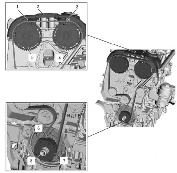
Pic. 5.41. Mounting marks (valve timing): 1 - alignment mark of the exhaust camshaft pulley; 2 - cover of the gas distribution mechanism drive with alignment marks; 3 - alignment mark of the intake camshaft pulley; 4 – a gear pulley of an inlet camshaft; 5 – a gear pulley of a final camshaft; 6 - alignment mark of the gear pulley of the timing gear drive on the crankshaft; 7 - toothed pulley of the timing belt on the crankshaft; 8 - crankshaft.
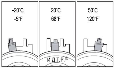
Pic. 5.42. The positions of the adjusting elements of the timing belt tensioner of the Duratec-V15 engine with a volume of 2.5 liters at different engine temperatures.
Visitor comments