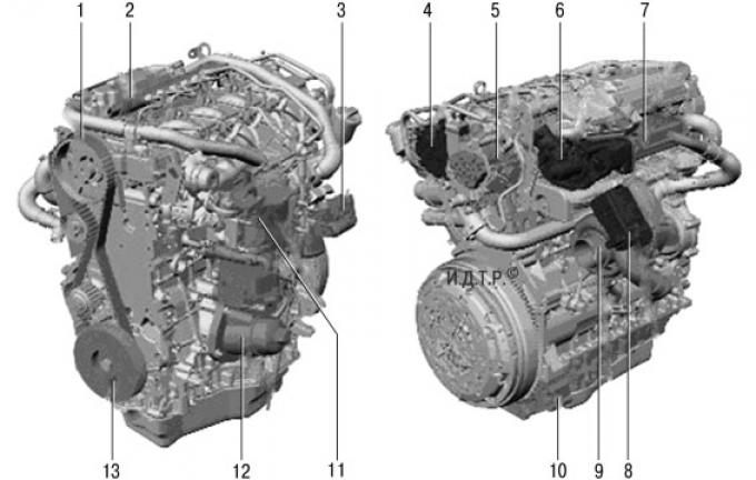
Fig. 5.48. Duratorq-TDCi engine with a volume of 2.2 l: 1 – timing belt; 2 – fuel injection system distribution manifold; 3 – Electronically controlled intake manifold flap; 4 – vacuum pump; 5 – fuel pump; 6 – Electrically controlled exhaust gas recirculation (EGR) system; 7 – EGR system radiator; 8 – electric actuator for adjusting turbocharger guide vanes; 9 – turbocharger with adjustable nozzle apparatus; 10 – oil pan extension; 11 – fuel filter; 12 – oil filter/oil cooler block; 13 – crankshaft damper.
The 2.2L Duratorq-TDCi engine (Fig. 5.48) is a four-cylinder, in-line, turbocharged diesel with two overhead camshafts, 16 valves, a balance shaft block for optimum smoothness, and an exhaust gas recirculation (EGR) system.
The cylinder block is made of cast iron, with cast cylinder liners and has double walls, which ensures high strength. In addition, an air jacket is additionally created, significantly improving noise insulation. The cylinder mirrors are bored directly in the cylinder block. To fix the cylinder head gasket, two holes are made in the cylinder block for the guide bushings.
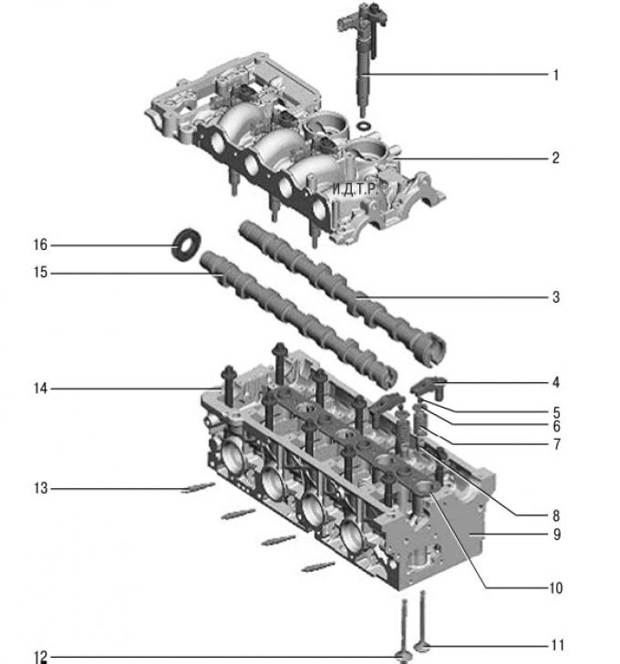
Fig. 5.49. Cylinder head of the 2.2 l Duratorq-TDCi engine: 1 – fuel injector; 2 – upper part of the cylinder head; 3 – exhaust camshaft; 4 – roller pusher; 5 – valve spring cracker; 6 – upper valve spring plate; 7 – valve springs; 8 – lower valve spring plate; 9 – lower part of the cylinder head; 10 – gasket; 11 – exhaust valves; 12 – intake valves; 13 – glow plug; 14 – cylinder head mounting bolts (10 pcs.); 15 – intake camshaft; 16 – exhaust camshaft oil seal.
The cylinder head (Fig. 5.49) is composite, aluminum, and consists of two parts. The lower part of the cylinder head is attached to the cylinder block with ten bolts. Reuse of the bolts is not permitted, as they have a programmed deformation when tightened.
The multilayer steel cylinder head gasket is manufactured in four thickness variations depending on the piston protrusion.
NOTE: The upper and lower cylinder head halves are matched to each other within their tolerances. They cannot be replaced separately.
Cylinder head cover with integrated crankcase ventilation valve. The seal between the head cover and the top of the cylinder head is made in the form of a flat gasket.
The camshafts are made of cast iron. The intake camshaft drives the vacuum pump at its rear end, and the exhaust camshaft drives the fuel pump at its rear end. The seal is a rubber O-ring.
The exhaust camshaft is driven by a toothed belt from the crankshaft, the intake shaft is driven by a chain from the exhaust camshaft. The chain is tensioned by a hydraulic tensioner.
The upper parts of the camshaft bearings are made in the upper part of the cylinder head. The camshafts rotate directly in aluminum bearings.
In the upper cover of the valve timing housing there is a hole for installing a special tool for fixing the toothed pulley of the exhaust camshaft when checking the correct installation of the valve timing.
The hydraulic timing chain tensioner is attached to the top of the cylinder head between the camshaft sprockets.
Oil pressure is transmitted to the hydraulic timing chain tensioner through a channel in the cylinder head. A pressure spring in the hydraulic timing chain tensioner provides the required chain pretension.
NOTE: A locking pin is provided on the chain tensioner to relieve chain pretension during maintenance work.
NOTE: After installing the upper cylinder head, make sure the hydraulic chain tensioner is in the loose position.
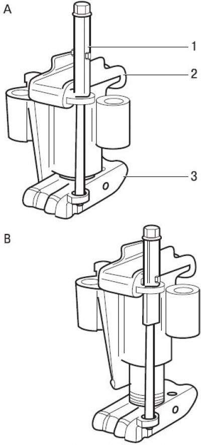
Fig. 5.50. Fixing and loosening the hydraulic tensioner of the timing chain: A – the chain tensioner is fixed; B – chain tensioner is loose; 1 – locking pin; 2 – Upper chain guide; 3 – lower chain guide.
To secure the hydraulic chain tensioner, lift pin 1 (Fig. 5.50) and then turn it 90°.
To pre-tension the hydraulic chain tensioner, turn the service pin 90° again.
The crankshaft has five main bearing supports. The corresponding cylinder number is stamped on the cover of each main bearing for identification.
The axial movement of the crankshaft is limited by four semicircular thrust washers, which are located on both sides of the middle main bearing. The thrust washers have lubrication grooves, which should face the main bearing.
Each main bearing housing and cap is provided with upper and lower liners. The upper liners have a hole and an annular groove for supplying oil under pressure from the main bearing through the crankshaft holes to the connecting rod bearings.
To create optimum crankshaft main bearing clearance, five lower main bearing shell thicknesses are available.
The balance shaft drive gear is hot pressed onto the third journal of the crankshaft.
The connecting rods are made of forged steel.
The upper head of the connecting rod is tapered on both sides, forming a cone. The conical shape improves the distribution of forces between the piston and the connecting rod during the combustion stroke. A bronze bushing is installed in the upper head of the connecting rod, in which an internal groove is made for supplying oil to the piston pin. The lower head of the connecting rod is composite. The cover is attached to the connecting rod with two bolts.
The piston is made of aluminum alloy and has three piston rings. A steel insert is installed in the groove of the upper piston ring for reinforcement.
NOTE: Piston rings must be installed so that the ring ends are at an angle of 120° (with a tolerance of 15–20°) from each other around the circumference of the piston.
The top two compression rings are stamped with the word "Top" to facilitate installation.
The working surface of the piston is graphitized to reduce friction against the cylinder bore.
To cool the pistons, piston cooling nozzles are installed in the lower part of the cylinder liners. These nozzles evenly spray engine oil under the piston bottom. Oil channels are located in the piston bottom. Sprayed oil penetrates these oil channels, providing the required piston cooling.
The balance shafts of the shaft balancing unit counteract the inertial forces (caused by the counter movement of the piston pairs) on the crankshaft.
NOTE: The balance shaft assembly must not be removed for maintenance.
The balance shaft block is located under the crankshaft. The block assembly is attached with eight bolts to the bottom of the cylinder block. The oil pump is located on the bottom of the balance shaft housing. The required clearance in the gear engagement between the driven gear of the balance shaft and the driving gear on the crankshaft is set using adjusting linings.
The balance shaft drive gear on the crankshaft causes the drive balance shaft to rotate in the direction opposite to the crankshaft rotation. The driven balance shaft rotates from the drive balance shaft in the direction coinciding with the direction of rotation of the crankshaft. The number of teeth on the balance shaft drive gear on the crankshaft is twice as many as on the mating gears of both balance shafts. Therefore, the gear ratio is 1:2.
The rotary oil pump is secured to the balance shaft block with four bolts. Another bolt, located in the mesh oil filter, secures the oil pump to the guide tube of the engine oil level indicator.
The pump is driven from the crankshaft by a chain.
The oil pump develops a maximum permissible oil pressure of approximately 6.5 bar and a maximum flow of 50 l/min.
The relief valve in the outlet channel of the oil pump protects the elements of the oil pump and the lubrication system from excess pressure in the system. The pressure limiting valve opens at a pressure of 8 bar. Excess oil flows back into the oil sump.
The oil filter/oil cooler unit is located under the intake manifold at the level of the third cylinder. A replaceable paper filter element is installed in the filter housing. Coolant from the cooling system is supplied to the oil cooler from the cylinder block. From the radiator, the coolant flow is directed to the thermostat.
The intake manifold is designed in such a way that the forced air is evenly distributed across all eight of its intake channels.
In addition, crankcase gases from the engine crankcase ventilation system and exhaust gases from the EGR (exhaust gas recirculation) system are fed into the intake pipe.
Sealing of the intake ports in the cylinder head is ensured: – for the four lower ports that create swirl – by means of an O-ring; - for the four upper channels, which create maximum filling, - using a rubber gasket.
The intake manifold is attached to the cylinder head with seven bolts.
The exhaust manifold is secured to the cylinder head with nine self-locking nuts.
Additionally, a spacer sleeve is installed on each exhaust manifold mounting stud. The spacers compensate for changes in the clearance between the exhaust manifold and the cylinder head when the exhaust manifold is heated or cooled.
The exhaust manifold has a connecting flange for installing a turbocharger and an exhaust gas recirculation (EGR) valve.
A heat shield is mounted above the exhaust manifold. It protects heat-sensitive parts in the exhaust manifold area.
In addition, the heat shield prevents skin burns in case of accidental contact with the hot exhaust manifold.
The geometry of the turbocharger guide vane is changed using an electrical actuator.
The turbocharger shaft is lubricated and, accordingly, cooled by engine oil through the supply line.
During operation, the turbocharger shaft rotation speed can reach 200,000 min⁻¹.
The EGR (exhaust gas recirculation) system recirculates a portion of the exhaust gases back into the fresh air flow entering the engine cylinders. The proportion of exhaust gases returned depends largely on the engine speed and engine load. Exhaust gas recirculation is particularly effective in the lower partial load range. Under favourable conditions, the recirculation proportion can exceed 60%. The EGR valve consists of a DC motor and a position sensor.
The engine cooling system circuit includes an exhaust gas recirculation (EGR) radiator. Cooling the EGR system reduces nitrogen oxide emissions.
The original article can be viewed on the portal: FordBook.ru