This system ensures compliance with modern standards for toxic emissions and evaporation of harmful substances while maintaining high driving performance and low fuel consumption.
The control device in the system is the electronic control unit (ECU, controller). Based on the information received from the sensors, the ECU calculates the parameters for regulating fuel injection and controlling the ignition timing. In addition, in accordance with the embedded algorithm, the ECU controls the operation of the electric motor of the engine cooling system fan and the electromagnetic clutch of the air conditioner compressor, performs the function of self-diagnosis of the system elements and notifies the driver of any malfunctions.
If individual sensors and actuators fail, the ECU switches on emergency modes to ensure engine operability.
The amount of fuel supplied by the injectors is determined by the duration of the electrical signal from the ECU. The electronic unit monitors engine condition data, calculates the fuel requirement and determines the required duration of fuel supply by the injectors (signal duration). To increase the amount of fuel supplied, the signal duration increases, and to reduce fuel supply, it decreases.
The engine management system, along with the electronic control unit, includes sensors, actuators, connectors and fuses.
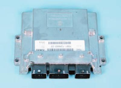
Electronic control unit (ECU) is connected by electrical wires to all the sensors of the system. Receiving information from them, the unit performs calculations in accordance with the parameters and control algorithm stored in the memory of the programmable read-only memory (EPROM), and controls the executive devices of the system. The program version recorded in the EPROM memory is designated by the number assigned to this modification of the ECU.
The control unit detects the fault, identifies and stores its code, even if the fault is unstable and disappears (e.g. due to poor contact). The engine management system fault indicator lamp in the instrument cluster goes out 10 seconds after the faulty unit is restored to working order.
After repair, the fault code stored in the control unit memory must be erased. To do this, disconnect the power supply to the unit for 10 seconds (remove the fuse of the power supply circuit of the electronic control unit or disconnect the wire from the negative terminal of the battery).
The unit supplies various sensors and switches of the control system with direct current of 5 and 12 V. Since the electrical resistance of the supply circuits is high, the control lamp connected to the system terminals does not light. To determine the supply voltage at the ECU terminals, use a voltmeter with an internal resistance of at least 10 MOhm.
The ECU is not suitable for repair; in case of failure it must be replaced.
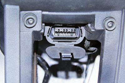
Diagnostic connector serves to output from the ECU memory the error codes detected during operation of the engine management system.
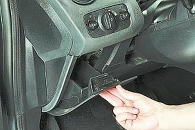
The diagnostic connector is located in the car's interior under the instrument panel on the left side (inside the small item box, under the hinged lid). A scanning device that reads fault codes can be connected to the diagnostic connector.
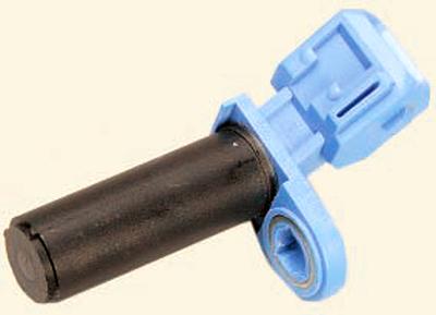
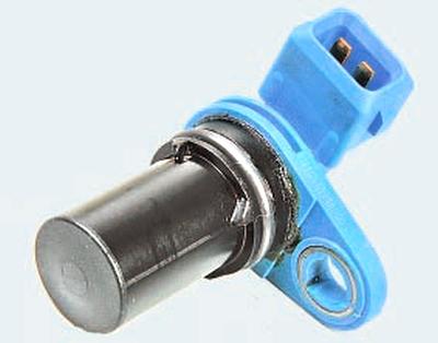
Crankshaft position sensor inductive type is designed to synchronize the operation of the electronic control unit with the TDC of the pistons of the 1st and 4th cylinders and the angular position of the crankshaft.
The sensor is installed at the rear of the engine opposite the timing teeth on the flywheel. The timing teeth are made on the surface of the flywheel at equal intervals.
One tooth is missing to create a synchronization pulse (the "reference" pulse), which is necessary to coordinate the operation of the control unit with the TDC of the pistons in the 1st and 4th cylinders.
When the crankshaft rotates, the teeth change the magnetic field of the sensor, inducing AC voltage pulses. The control unit determines the crankshaft rotation frequency based on the sensor signals and sends pulses to the injectors.
If the sensor fails, the engine cannot be started.
Camshaft position sensors (phase sensors)) inductive type determine the TDC of the compression stroke of the piston of the 1st cylinder and serve to organize phased fuel injection in accordance with the order of operation of the cylinders. In engines equipped with a variable valve timing system, the signals from the sensors of the intake and exhaust camshafts are also used by the controller to control the change in valve timing depending on the engine operating mode.
If a fault occurs in the circuit of any of the sensors, the controller enters its code into its memory and turns on the signal lamp.
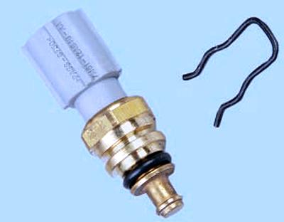
Coolant temperature sensor is installed in the coolant distributor housing on the rear side of the engine. The sensor's sensitive element is a thermistor, the electrical resistance of which changes inversely proportional to the temperature. At low coolant temperatures (–40°C), the thermistor's resistance is about 100 kOhm; when the temperature rises to +130°C, it decreases to 70 Ohm.
The electronic unit supplies the temperature sensor circuit with a constant reference voltage. The sensor signal voltage is maximum when the engine is cold and decreases as it warms up. Based on the voltage value, the electronic unit determines the engine temperature and takes it into account when calculating the injection and ignition adjustment parameters.
If the sensor fails or there are problems in its connection circuit, the ECU sets a fault code and remembers it.
In addition to the above, the sensor also indirectly serves as a coolant temperature gauge sensor in the instrument cluster. Based on the information from this sensor, the electronic engine control unit changes the position of the gauge needle.
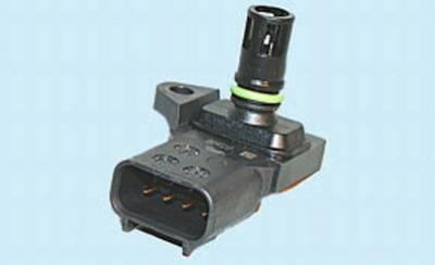
Combined manifold absolute pressure and intake air temperature sensor is made in the form of a variable resistor sensitive to pressure changes. It records the change in pressure in the intake pipe in accordance with changes in load and engine speed. Depending on the information received from the sensor, the ECU records the amount of injected fuel and the ignition advance angle.
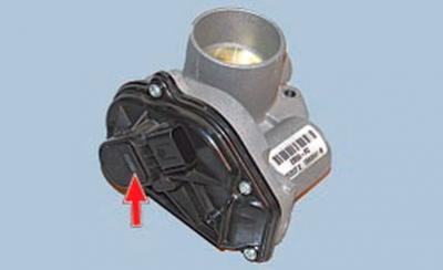
Throttle Position Sensormade as a single piece with the throttle body cover.
The sensor is a potentiometer, to one end of which the "plus" of the supply voltage (5 V) is supplied, and the other end is connected to the "ground".
From the third output of the potentiometer (from the slider) the output signal goes to the electronic control unit.
When the throttle valve is turned (according to the action on the accelerator pedal), the voltage at the sensor output changes. When the throttle valve is closed, it is below 0.5 V. When the valve opens, the voltage at the sensor output increases, when the valve is fully open, it should be more than 4 V.
By monitoring the output voltage of the sensor, the ECU adjusts the fuel supply depending on the throttle opening angle (i.e., at the driver"s request).
The throttle position sensor does not require adjustment, since the control unit perceives idle speed (i.e., completely closed throttle valve) as a zero mark.
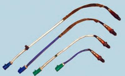
Oxygen concentration sensors (lambda probes) screwed into the threaded holes of the catalytic converter. On Ford Mondeo cars, depending on the engine type, two or four oxygen concentration sensors are installed:
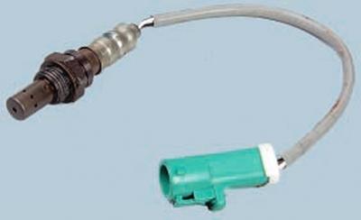
– one or two sensors to control the composition of the fuel-air mixture (at the entrance to the neutralizers)…
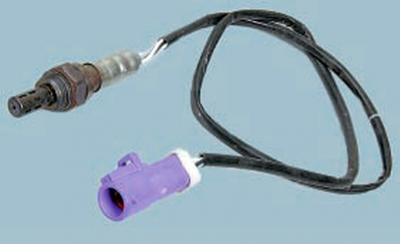
…and one or two more diagnostic sensors to assess the efficiency of the neutralizers (at the output).
The sensor's metal flask contains a galvanic element washed by the exhaust gas flow. Depending on the oxygen content in the exhaust gases, the sensor's signal voltage changes as a result of combustion of the fuel-air mixture.
The sensors differ in parameters and have different markings. If at least one of the oxygen concentration sensors is faulty, the toxicity of exhaust gases can increase sharply, and fuel consumption can increase.
For ease of replacement, the sensors are distinguished by the color of the pads. The pad of the sensor wiring harness at the input to the neutralizer (control) is green, and at the output from the neutralizer (diagnostic) is purple (or blue).
Information from each sensor is sent to the control unit in the form of low (from 0.1 V) and high (up to 0.9 V) level signals. With a low level signal, the control unit receives information about a high oxygen content. A high level signal indicates a low oxygen content in the exhaust gases.
By constantly monitoring the voltage of the sensor signals, the control unit adjusts the amount of fuel injected by the injectors. When the sensor signal level at the input of the neutralizer is low (lean fuel-air mixture), the amount of fuel supplied increases; when the signal level is high (rich mixture), it decreases. If the difference between the signal levels of the sensors at the input and output of the neutralizer is less than the values allowed for this operating mode, the control unit identifies a malfunction of the catalytic converter.
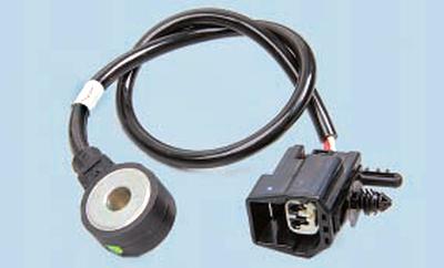
Knock sensor the Duratec Ti-VCT engine is attached to the top of the cylinder block in the area between cylinders 2 and 3, while the other engines have two sensors installed in the areas between cylinders 1 and 2 and between cylinders 3 and 4. The sensor detects abnormal vibrations (detonation shocks) in the engine.
The sensitive element of the knock sensor is a piezoelectric crystal plate. During detonation, voltage pulses are generated at the sensor output, which increase with the increase in the intensity of detonation shocks. The ECU, based on the sensor signal, regulates the ignition advance to eliminate detonation flashes of fuel.
During operation, the ECU also uses data on the vehicle speed received from the anti-lock braking system (ABS) control unit.
WARNINGS: Before removing any fuel injection control system components, disconnect the negative battery cable.
Do not start the engine if the battery cable terminals are not tightly tightened.
Never disconnect the battery from the vehicle's electrical system while the engine is running.
When charging the battery, disconnect it from the vehicle's electrical system.
Do not expose the ECU to temperatures above 65°C when operating and above 80°C when not operating (e.g. in a drying chamber).
It is necessary to remove the ECU from the car if this temperature is exceeded.
Do not disconnect or connect wires to the ECU when the ignition is on.
Before performing electric welding work on the vehicle, disconnect the wires from the battery and the wiring harness connectors from the ECU.
All voltage measurements should be performed using a digital voltmeter with an internal resistance of at least 10 MΩ.
The electronic components used in the fuel injection system are designed for very low voltage and are therefore easily damaged by electrostatic discharge.
To avoid damaging the ECU, do not touch its terminals with your hands.
In all cases, a special scanner is required to diagnose the engine management system, so if any system malfunctions occur, contact a specialized service center.