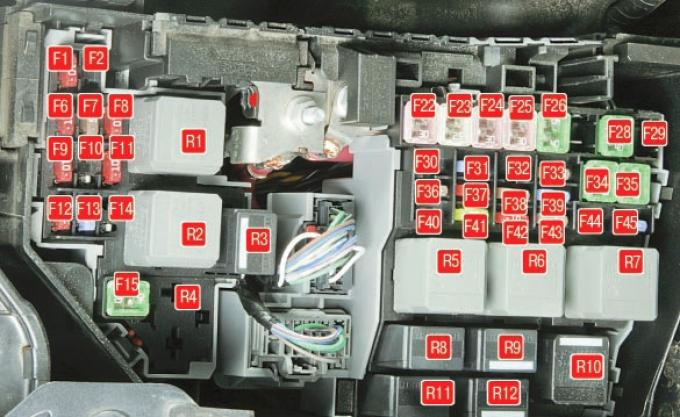
Fig. 10.1. Location of fuses and relays in the mounting block installed in the engine compartment (top view).
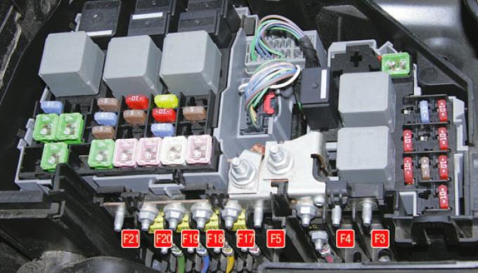
Fig. 10.2. Location of fuses and relays in the mounting block installed in the engine compartment (side view, protective covers of fuse links removed).
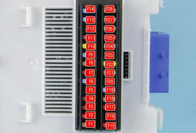
Fig. 10.3. Location of fuses in the central mounting block located in the passenger compartment.
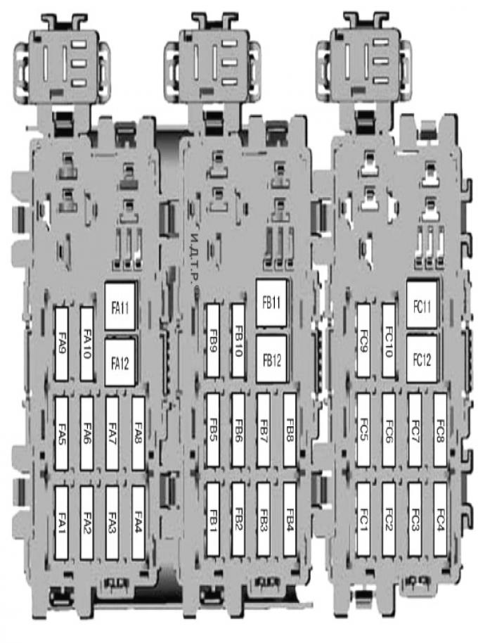
Fig. 10.4. Location of fuses in the rear mounting block, installed in the luggage compartment of cars with sedan and hatchback bodies.
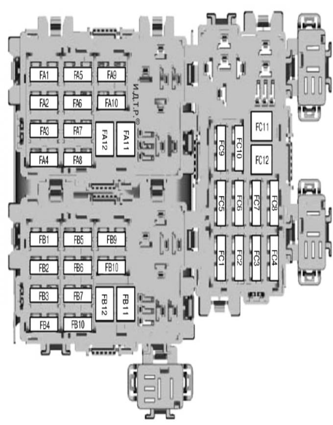
Fig. 10.5. Location of fuses in the rear mounting block installed in the luggage compartment of station wagons.
Most of the power circuits of the car's electrical equipment are protected by fuses. Headlights, fan motors, fuel pump and other powerful consumers are connected via relays.
Fuses and relays are installed in mounting blocks, which are located in the vehicle interior and underhood space.
Most fuses and relays are installed in the fuse and relay mounting block (Fig. 10.1 and 10.2), located in the underhood space on the left side, near the battery and air filter. The purpose of the fuses and relays is given in Table 10.1.
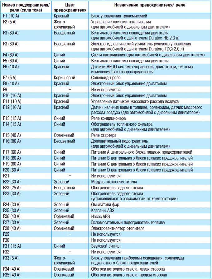
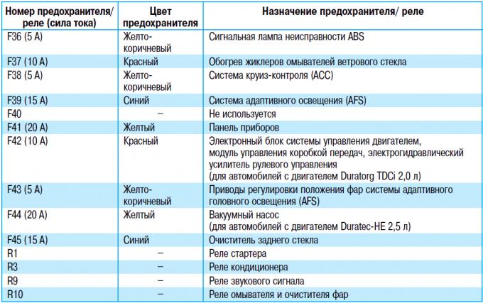
NOTE: Fig. 10.1 and 10.2 show the maximum possible set of fuses and relays.
On a specific vehicle, some of them may be missing (depending on the vehicle"s configuration).
Table 10.1 shows the purpose of only those relays that may need to be replaced by the driver to ensure traffic safety and health. The remaining relays, if faults occur, must be replaced at a service center after diagnostics.
Fuses for the lighting system, sound signaling, climate control, etc. are located in the central fuse box, installed on the cover of the GEM multifunctional electronic unit (Fig. 10.3), which, in turn, is installed under the instrument panel on the right.
The purpose of the fuses is given in Table 10.2.
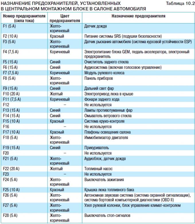
NOTE: Fig. 10.3 shows the maximum possible set of fuses. Some of them may be missing on a specific vehicle (depending on the vehicle configuration).
Fuses for control systems of electric windows, locks, exterior mirrors, front seat adjustment mechanisms, parking sensors, etc.
are located in the rear fuse box, installed under the left side trim of the trunk (Fig. 10.4 and 10.5). The purpose of the fuses is given in Table 10.3.
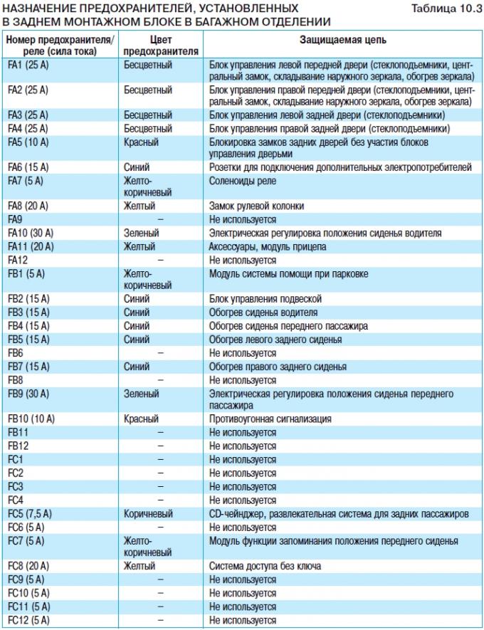
NOTE: Fig. 10.4 and 10.5 show the maximum possible set of fuses. Some of them may be missing on a specific vehicle (depending on the vehicle configuration).
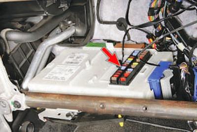
The central fuse box is located on the top cover of the multi-function electronic unit, installed on the right under the instrument panel (under the glove compartment).
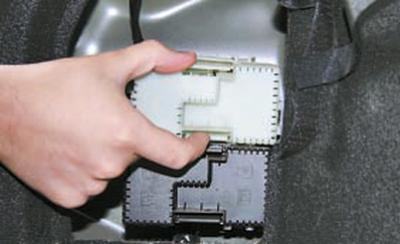
NOTE: Shown with instrument panel removed for clarity.
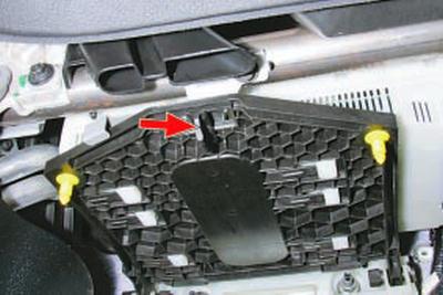
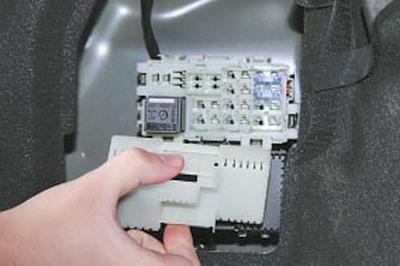
1. To access the fuses in the central mounting block, turn the multi-function electronic unit base lock a quarter turn to the right, remove the base from the holders and lower it down.
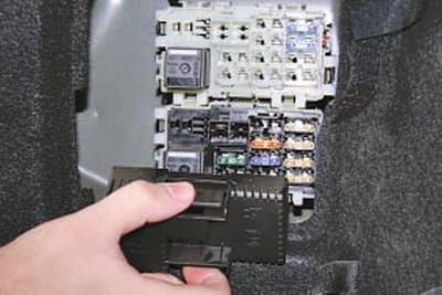
NOTE: For ease of use of the unit, its housing can be pulled out by rearranging the housing protrusions in the grooves of the supporting brackets.
This will give you access to the central fuse box.
2. Before replacing a blown fuse, find out the reason for its blown fuse and eliminate it. When searching for a fault, look at the circuits specified in Table 10.2 that this fuse protects.
WARNING: Do not replace fuses with jumpers or fuses rated for a different amperage or with homemade jumpers - this may cause damage to electrical equipment and even fire.
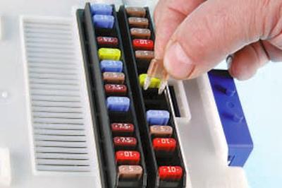
3. Remove the replacement fuse by gently rocking it from side to side.
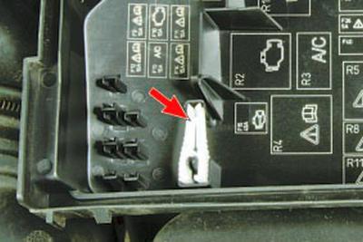
NOTE: It is more convenient to remove the fuse using special tweezers installed in the clamp on the back of the cover of the mounting block located in the engine compartment.
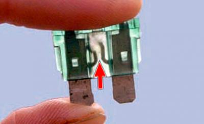
4. This is what a blown fuse looks like (the jumper inside the holder, shown by the arrow, has blown and opened). To replace the fuse, use a spare fuse of the same rating (and color).
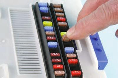
5. To install a new fuse, insert its contacts into the block holders and, pressing on it from above, push it in until it stops.
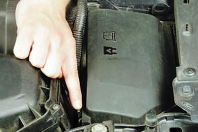
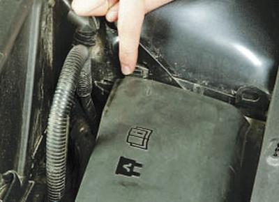
6. To access the fuses and relays of the fuse box in the engine compartment, push aside the two latches of its cover on one side…
7….and on the other hand…
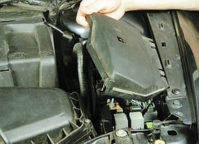
8….and remove the lid.
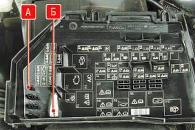
NOTE: The relay and fuse layout diagram is applied to the inside of the cover of the relay and fuse box located in the engine compartment. Tweezers B for removing fuses from the fuse boxes are also attached there, and sockets A for attaching spare fuses are located next to it.
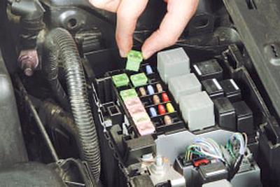
9. If replacement is necessary, remove the fuse link…
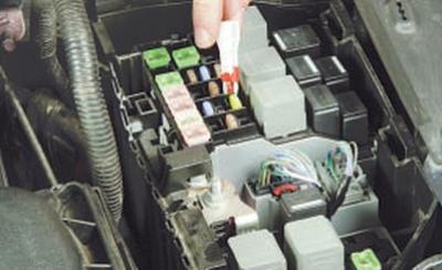
10….fuse…
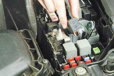
11….or a relay, swinging it from side to side.
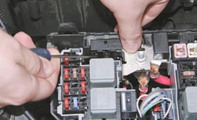
12. To gain access to the fuse links located on the side of the mounting block (see Fig. 10.2), use a screwdriver to press the fasteners of the side protective cover…
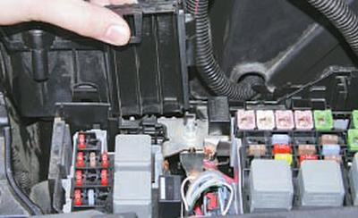
13….and remove it by pushing it upwards along the grooves of the block body.
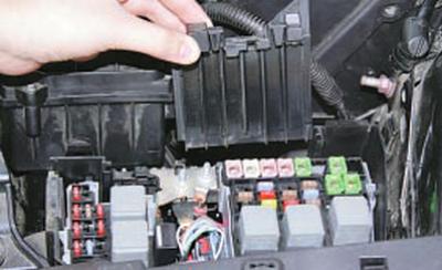
14. Remove the second cover in the same way.
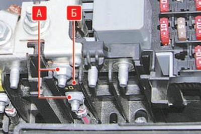
15. To replace the fuse link B, unscrew the two nuts A that secure it, install the new link and secure it with nuts.
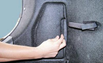
16. To gain access to the rear fuse box, press the hatch cover latch in the left side trim of the luggage compartment…
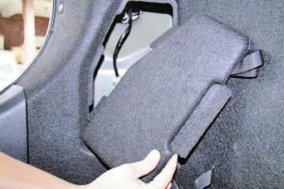
17….and remove the cover.
18. Squeeze the latches on the sides of the fuse box covers..
19….remove the covers of the upper…
20….and the lower blocks.
NOTE: Depending on the vehicle configuration, three mounting blocks may be installed. The covers of all blocks are removed using the same techniques.
21. Replace the blown fuse in the same way as you did for the central mounting block and the block located in the engine compartment (see above in this subsection).
22. Install the parts in the reverse order of removal.
Content was created using data from this website FordBook