General description
1. The EGR system is designed to return small portions of the exhaust gas to the combustion cycle and thus reduce nitrotoxins in emissions. The amount of exhaust gas re-burned and the cycle time depends on various factors - engine speed, altitude, manifold vacuum, back pressure in the exhaust system, coolant temperature and throttle angle. All EGR valves are vacuum actuated, a vehicle specific vacuum line diagram is shown on the Emission Control Information label in the engine compartment.
2. Tauras / Sable vehicles use two types of EGR valves, the electronic type is used on four-cylinder engines, and the electronic pressure return valve (PFE), used on California 3.0LV6 and 3.8LV6 engines.
Electronic EGR valve for four-cylinder engine
3. The electronic EGR valve controls the exhaust gas flow using the EVP sensing element located at the top of the valve. The valve is actuated by a vacuum signal from dual valves - EGR solenoids or an electronic vacuum regulator acting on the valve diaphragm. As soon as the vacuum suction overcomes the force of the spring, the diaphragm is activated, which lifts the valve from its seat and allows the exhaust gas to be recirculated. The amount of gas released depends on the position of the valve. The EVP sensor sends an electrical signal to the ECA system indicating valve position.
Electronic EGR valve make-up pressure (PFE)
4. PFE valve - the same as EGR, only a sensitive back pressure tube is connected to it. The valve is used in conjunction with a pressure transducer which provides pressure feedback to the EEC - IV processor. The flow through the valve is proportional to the pressure drop at the outermost, sharp-edged orifices.
5. Make sure all vacuum hoses are properly connected and securely attached. Replace cracked, broken, deformed hoses.
6. Make sure there is no vacuum in the EGR valve at idle at normal engine operating temperature.
Note: The EVR solenoid on four cylinder engines has a permanent internal leak. You will find a slight vacuum signal (it will be less than 21/2 inches of mercury at idle).
7. Install the tachometer in accordance with the manufacturer's instructions.
8. If the vehicle is equipped with a V6 engine, pull out the bleed air valve connector (see if necessary chapter 4).
9. Disconnect the vacuum supply hose from the lower EGR valve. Install a plug in the hose.
10. Set the transmission to neutral, start the engine. warm up and leave to work on canvas.
Note: Do not increase the engine idle speed. If it is too high or low, it should be adjusted.
11. Attach a hand vacuum pump to the EGR vacuum valve nipple and slowly apply vacuum to 5-10 inches of mercury.
12. The valve will need to be replaced if any of the following occur while creating a vacuum in the EGR valve:
A) the engine will stall.
b) idle speed will drop by more than 100 rpm.
V) idle speed will not recover to normal±25 rpm.) after connecting the vacuum line.
14. Disconnect the vacuum pump and connect the EGR valve vacuum line.
Replacing elements
15. Disconnect a wire from the minus plug of the accumulator.
16. On four-cylinder engines, remove the electrical connector from the EVR sensor socket in the EGR valve.
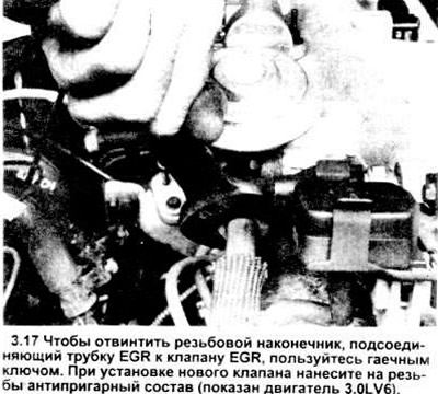
17. Using a wrench, unscrew the threaded lug. connecting tube and EGR valve (see picture).
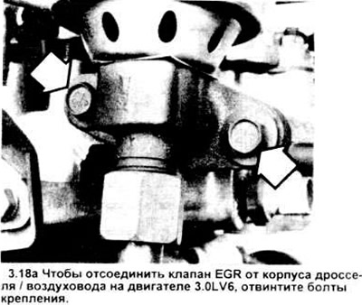
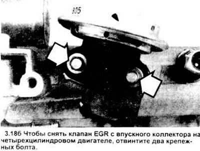
18. Unscrew the EGR valve mounting bolts (see pictures) and disconnect the valve and gasket from the intake manifold. Throw away the old gasket.
19. If you are going to replace the EGR valve without changing the EVR sensor on a four-cylinder engine, remove the sensor from the old valve (see section 2) and install it on the new valve.
20. Installation is carried out in the reverse order of disassembly. Ensure gasket mating surfaces are clean and use a new valve gasket.
Note: Apply a non-stick compound to the threaded surfaces of the EGR tube.
Visitor comments