General description
1. Air control system entering the manifold (see picture) reduces the content of carbon monoxide and hydrocarbons in the exhaust gases by injecting fresh air into the hot exhaust gas leaving the exhaust pipe.
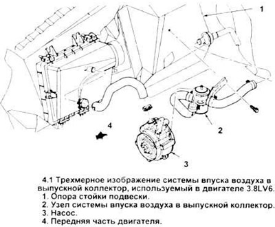
When fresh air is mixed with hot exhaust gas, oxidation increases, the concentration of hydrocarbons and carbon monoxide decreases, which are converted into harmless carbon dioxide and water.
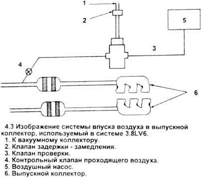
2. All vehicles with 3.8LV6 engines use a manifold air control system that directs the air stream either up to the exhaust manifold control valve or down to the lower section check valve and two-way catalyst.
3. The air control valve is used to direct the flow upwards or downwards. The passing air valve exhausts it to the atmosphere. These two valves in the 3.8LV6 engine are combined into one unit (see picture).
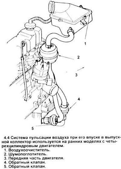
4. Early models of four-cylinder engines are equipped with an injection system called an air pulser or intake system - II (see picture). This design uses the natural air pulsation that occurs in the exhaust system to force air into the exhaust manifold and catalyst through the air pulsation valves.
Examination
Air pump
5. Check and adjust drive belt tension (see chapter 1).
6. Disconnect the air supply hose from the air passage valve inlet.
7. The pump then works satisfactorily when the air flow is felt at its outlet with the engine idling, this flow increases with increasing engine speed.
8. If the pump does not meet the above conditions, replace it with a new one or disassemble the assembly.
Combination of through air valves / and air flow control
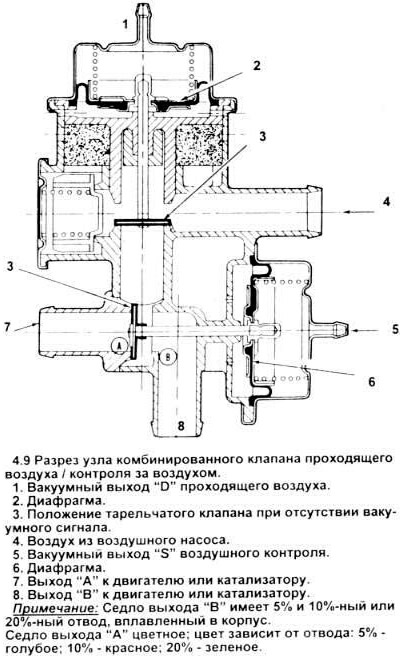
9. Tag and disconnect hoses from these valve combination outlets (see picture).
10. Disconnect the vacuum hose from the combination valve, insert a plug into it.
11. With the engine running at 1500 rpm, check that air is escaping from the passing vents.
12. Pull out and disconnect the vacuum hose from the outlet "ABOUT" then disconnect and insert the plug into the outlet hose "S".
13. Instantly disconnect the hose leading to the outlet "D" make sure it has a gap.
14. Connect a hose to outlet D.
15. At engine speeds of 1500 rpm, make sure that air is escaping from the hole "IN", and in the hole "A" no air flow.
16. Connect a piece of hose to the outlet "S".
17. At engine speeds of 1500 rpm, apply vacuum to this hose and then make sure that air comes out of the outlet "A".
18. Reconnect all hoses. Don't forget to remove the plug from the outlet hose "S", before connecting it.
19. If all of the above conditions are not met, replace the combination valve with a new one.
Check valve
20. Disconnect the hoses from both ends of the check valve.
21. Blow the valves through both ends, making sure the air flows in one direction only.
22. If air is flowing in both directions or not at all, replace the check valve with a new one.
23.. When connecting the valve, remember that. that it needs to be installed in a certain direction.
Noise test of the air intake system in the exhaust manifold
24. When intake into the manifold under normal conditions, the pitch of the sound rises as the engine speed increases. To determine if this noise is due to a breakdown in the injection system, disconnect the drive belt (making sure that its tension is normal) and inspect the engine. If the noise disappears, go to the following diagnostics.
Caution: The test will only make sense if the pump has traveled at least 500 miles (those. vehicle miles). Install the drive belt (Chapter 1).
25. If the belt makes a lot of noise:
A) check belt tension (see chapter 1);
b) check the pump, replace if necessary;
V) the pulley fastening may be loose Tighten the fastening bolts. as required;
G) it is possible that the support brackets or bolts are loose, broken, or missing altogether. Tighten or replace if necessary.
26. If you hear a strong mechanical noise:
A) it is possible that the fixing bolt is too tight;
b) drive belt too tight (see chapter 1);
V) the adjusting lever of the air pump is faulty; if necessary, remove it;
G) if the adjusting lever is worn, replace it.
27. If you hear intense noise from the air intake system to the exhaust manifold (whistling or buzzing sounds):
A) check for possible leaks in the hoses;
b) hose may be loose, punctured or kinked - fix or replace hose and/or clamps as required;
V) check if any of the hoses are touching other parts of the engine and adjust or find a different position for the hose to prevent further contact;
G) the airflow valve may be inoperative (see paragraph 9) replace it if necessary;
d) check the operation of the non-return valve (see paragraph 20), replace if necessary;
e) check and tighten loose pump or pulley fasteners;
and) check the pump outlet tip - it should be rigid, not bent. Inspect the tip and free of all extraneous air passage. Replace the bent tip;
h) check the air bleed through the through air valve (only at idle). On many vehicles, the exhaust manifold air intake system has been designed to bleed air at idle and thus prevent the catalytic converter from overheating. This condition is normal. Before proceeding further, determine that the noise stabilizes at higher rpm;
And) check the air bleed through the through air valve (slow and idle reset).
On many vehicles, air from the intake system is vented to an air cleaner or a separate silencer. Make sure the hoses are intact and connected correctly.
28. If a loud noise is heard in the pump, make sure the pump has been sufficiently run in (at least 500 miles). Check for possible wear and damage to the pump, replace if necessary.
Replacing elements
29. To replace the elements of the through air valve, air suction control valve of the check valve, combined control air through the control valve or silencer, first mark, then disconnect the hoses leading to them, replace the defective elements, then reconnect the hoses to the appropriate outlets. The hoses must be in good condition, otherwise they must be replaced with new ones.
30. To replace the air pump, first loosen the corresponding engine drive belts (see chapter 1), then remove the failed pump from the support bracket. Label all wires and hoses when you remove them.
31. When replacing check valves on an air pulsation system (intake system II), use the reverse key.
32. After installing a new pump, adjust the tension of the belts (see chapter 1).
Visitor comments