Forced crankcase ventilation system (PVC)
Examination
1. The procedure for checking system components is presented in chapter 1.
Component Replacement
Hose connecting the air cleaner to the cylinder head
2. Disconnect the hose from the head cover and air cleaner. Install a new hose.
Positive crankcase ventilation valve
3. This valve is installed in the separator. Valve access (if you have the right tool) possible immediately after removing the fuel afterburning system assembly. Otherwise, follow the instructions in point 4 (see below).
Oil separator
4. Remove the exhaust manifold (chapter 2A or 2B). After that, the positive crankcase ventilation valve can be removed and flushed or replaced if necessary (see chapter 1).
5. Turn out bolts of fastening of an oil separator from the block of cylinders and remove it. Remove and discard the gasket.
6. Flush or replace the oil separator (see chapter 1).
7. Install the separator on a new gasket and tighten the fasteners to the required torque.
8. Perform other installation operations in the reverse order of removal. If you removed the lower hose from the radiator to remove the exhaust manifold, then fill the cooling system with liquid (Chapter 1). Start the engine and after it has warmed up, check for leaks from the exhaust system and the coolant level.
Fuel Evaporation Control System (WHALE)
Examination
9. Symptoms such as unreliable idling, as well as lack of dynamic qualities, may occur if the canister purge valve is faulty, the canister is damaged, or the hoses are damaged or incorrectly connected. Check the fuel filler cap for damage or deformation of the gasket.
10. Fuel leaks or fuel odor can be caused by leaking fuel lines, damaged canister, faulty purge valve, disconnected, misplaced, kinked or damaged steam line or control hose.
11. Inspect all adsorber connection hoses for breaks, leaks, and cracks along their entire length. Repair or replace as necessary.
12. Inspect the adsorber. If it is cracked or otherwise damaged, replace it. Inspect the bottom of the canister for fuel leaks. If leaks are found, replace the adsorber, check the hoses and make sure they are properly laid.
13. If you suspect the purge valve is defective, disconnect its electrical connector and disconnect its vacuum hose. Connect the accumulator directly to the valve terminals. When the valve solenoid is energized, air can pass through it, and when the solenoid is de-energized, air cannot pass through. Another way to check: connect an ohmmeter to the solenoid terminals and compare the readings with the Specifications. In case of malfunction, replace the valve.
14. Subsequent checks must be performed by dealers.
Component Replacement
Canister purge valve
15. Disconnect the negative battery cable (paragraph 1 chapter 5A). For improved access on models with 4-cylinder engines, the intake duct plenum can be removed (chapter 4). On models with V-shaped 6-cylinder engines, remove the ignition coil (gp.5B).
16. Disconnect the valve electrical connector (see fig.3.16). Detach the valve from the baffle, and then disconnect its vacuum hoses and remove the valve.
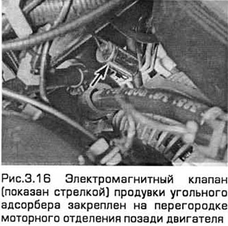
17. Installation - in the reverse order of removal.
Carbon canister - Sedan and Hatchback models
Note: Before you begin, make sure you have all the necessary equipment.
18. Remove the fuel tank (chapter 4A).
19. Place the rear of the vehicle on supports. Then support the rear suspension beam with a jack. Remove the wheels and turn out the bolts of the upper support of each rear suspension strut (two on each support - see chapter 10).
20. White paint (but not a sharp instrument) mark the position of the nut relative to the bottom. Remove the four fixing screws (see fig.3.20). Lower the beam on the jack by about 75 mm and place a reliable support under it.
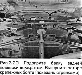
Note: Do not work under the vehicle if it is only supported by a jack!
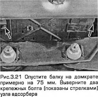
21. Turn out two fixing bolts of knot of an adsorber located behind (see fig.21).
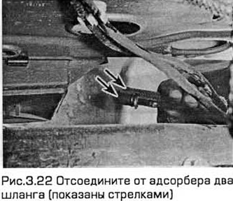
22. Disconnect two hoses from the adsorber, considering which side they are installed (see fig.3.22).
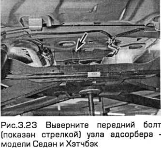
23. Turn out a forward bolt of knot of an adsorber. Remove adsorber (see fig.3.23).
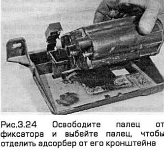
24. Release the pin from the retainer and knock out the pin to separate the adsorber from its bracket (see fig.3.24).
25. When installing, fix the adsorber on the bracket and fix this assembly in the car. Tighten the bolts securely, attach two hoses to the corresponding nozzles.
26. Move the beam to the place of its installation and insert the bolts, and then lightly tighten them.
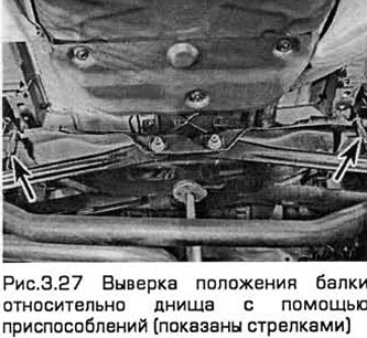
27. After that, the beam must be set relative to the bottom. Ford recommends tool 15-097 for this. It consists of a pair of conical guides and a fixing unit for this device on the beam during its installation (see fig.3.27). However, the working diameters of the guides are 20.4 mm, and the holes for them in the beam and the body have a diameter of 21 mm and 22 mm, respectively. Therefore, during assembly, a significant gap will appear. If you do not have such a device, expose the beam by eye, aligning its holes with the holes in the body and focusing on the marks made during removal. It is also possible to use a tapered rod, such as a clutch disc centering tool or a high wrench socket of the appropriate size, to align the beam and the body.
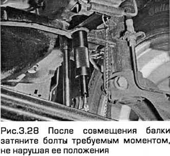
28. After aligning the beam, tighten the bolts to the required torque (chapter 10), without violating its provisions (see fig.3.28). After tightening the bolts, repeat the alignment check of the beam with the body.
29. Perform the remaining installation operations in the reverse order of removal,
30. Please note that after removal and installation of the beam, it is necessary to check and adjust the installation of wheels and steering angles as soon as possible. This needs to be done by experts.
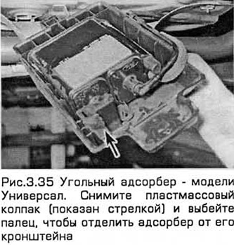
Coal adsorber - Universal models
31. Disconnect the negative battery cable (paragraph 1 chapter 5).
32. Raise the back of the car and place it on supports.
Note: Do not work under the vehicle if it is only supported by a jack!
33. Disconnect two hoses from the adsorber, considering which side they are installed on.
34. Turn out a bolt of fastening of knot of an adsorber. Remove the adsorber by unfastening it from the front support.
35. Remove the plastic cap and knock out a finger to separate the adsorber from its bracket (see fig.3.35).
36. When installing, fix the adsorber on the bracket and fix this assembly in the car. Tighten the bolts securely, attach two hoses to the corresponding nozzles.
Exhaust gas recirculation system (RVG)
Examination
RVG valve
37. Start the engine and bring it to idle.
38. Disconnect the vacuum hose from the RVG valve and install a manual vacuum pump in its place.
39. Create a vacuum in the RVG valve. The vacuum must be maintained, and the engine will become unstable.
- A) If vacuum does not persist and engine performance does not deteriorate, replace valve and retest.
- b) If the vacuum persists but engine performance does not deteriorate, remove the RVG valve and inspect it and the intake manifold for blockage. Clean or replace components and recheck.
RVG system
40. Subsequent system checks require special equipment and must be performed by dealers.
Component Replacement
Note: The following components become very hot when the engine is running. Therefore, before starting maintenance, you must wait until the engine has completely cooled down.
RVG valve
41. Disconnect the negative battery cable (paragraph 1 chapter 5).
42. On models with 4-cylinder engines, remove the air flow meter and resonator (chapter 4). On V-6 models, remove the idle speed control valve.
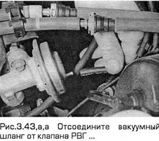
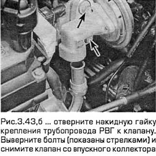
43. Disconnect the vacuum hose, unscrew the nut securing the RVG pipeline to the valve. Remove the two valve mounting bolts and remove the valve from the intake manifold (see Fig. 3.43, a, b). When removing the valve, be careful not to damage or bend the pipe end. Note that the valve gasket must always be replaced after it has been removed.
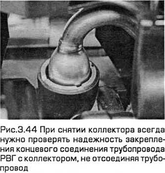
44. Please note that the metal pipe connecting the valve to the manifold is not supplied separately from the manifold. This pipe does not need to be disconnected. But when removing the manifold, you should always check the reliability of fixing the end connection of the pipe (see fig.3.44).
45. Check the valve for sticking and deposits. If these signs are found, flush the valve or replace it.
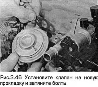
46. Installation - in the reverse order of removal. Apply anti-seize compound to the threads of the union nut. Install a new gasket and tighten the valve bolts to the correct torque (see fig.3.46).
RVG pipeline - models with 4-cylinder engines
47. Disconnect the negative battery cable (paragraph 1 chapter 5).
48. Remove the air mass meter and (where needed) resonator (chapter 4),
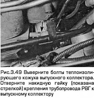
49. Turn out bolts of a heat-insulating casing of a final collector and remove both its parts or move them aside for access to an end part of the pipeline. Loosen the union nut securing the pipeline to the exhaust manifold (see fig.3.49).
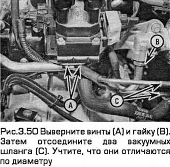
50. Turn out two screws of fastening of the pipeline to an arm of the coil of ignition. Then disconnect the two vacuum hoses. Please note that they differ in diameter in order not to confuse them during installation. Loosen the union nut securing the RVG pipeline to the valve (see fig.3.50). Remove the pipeline.
51. Check the condition of both hoses and replace them if necessary (Chapter 1). Please note that in the event of an intense backflash due to clogging of the exhaust system, both hoses must be replaced and their connection on the pipeline must be thoroughly flushed.
52. Installation - in the reverse order of removal. Install the hoses to the appropriate fittings. Apply anti-seize compound to the nut threads. Tighten nuts. Tighten the two screws to the required torque.
RVG pipeline - models with V-shaped 6-cylinder engines
53. Disconnect the idle air control valve pipe from the air cleaner and upper section of the intake manifold.
54. Turn away a cap nut of fastening of the RVG pipe from the RVG system valve and disconnect a pipe.
55. Chock the front wheels. Raise the rear and place it on supports. Remove the front left wheel and its wheel arch locker.
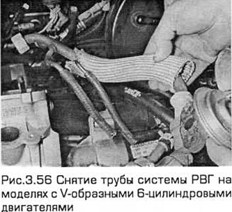
56. Remove the RVG system pipe from the exhaust manifold and remove it from the vehicle (see fig.3.56).
57. Installation - in the reverse order of removal. Apply anti-seize compound to the nut threads at both ends of the pipe.
Solenoid valve RVG
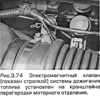
Note: It is secured with two machine screws and has a larger top than the afterburner solenoid valve next to it. Keep this in mind when attaching vacuum hoses.
58. Disconnect the negative battery cable (paragraph 1 chapter 5).
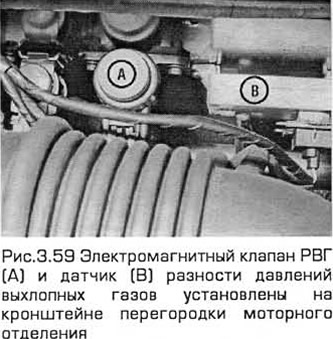
59. Remove the air mass meter and (where needed) on models with 4-cylinder engines, the resonator (chapter 4). You can remove the intake duct chamber to improve access (see fig.3.59).
60. Disconnect the valve electrical connector, releasing it from the retainer. Remove the two screws and remove the valve from the support bracket located on the baffle. Then tag and disconnect the two vacuum hoses.
61. Installation - in the reverse order of removal. Install the hoses in place.
Exhaust pressure difference sensor
62. This sensor should be checked by dealers.
63. On models with 4-cylinder engines, the resonator can be removed to improve access (chapter 4).
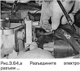
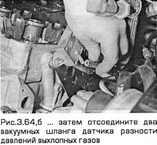
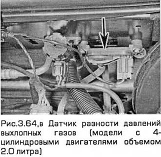
64. Disconnect the electrical connector, releasing it from the retainer. Remove two screws. Remove the sensor from the bracket mounted on the bulkhead (on models with 4-cylinder engines) or on the left side of the rear block head (on models with V-shaped 6-cylinder engines). Then disconnect the two vacuum hoses. Please note that the hoses differ in diameter so as not to confuse them during installation (see fig. 3.64, a-c).
65. Check the condition of both hoses and replace if necessary (see chapter 1).
66. Installation - in the reverse order of removal. Hoses must be securely fixed on the nozzles.
Fuel afterburning system
Examination
67. Due to a malfunction of the system, symptoms such as unreliable idling, stalling, as well as lack of dynamic quality can occur.
68. Inspect all hoses/pipes connecting filter housing and valve for kinks, leaks, and cracks along their entire length. Repair or replace as necessary.
69. Inspect the filter housing and piping. If cracks or other damage are found, replace the defective component.
70. If you think the valve "air injection" defective, disconnect its electrical connector and disconnect its vacuum hoses. Connect the accumulator directly to the valve terminals. When the valve solenoid is energized, air can pass through it, and when the solenoid is de-energized, air cannot pass through. Another way to check is also possible: connect an ohmmeter to the solenoid terminals and compare the readings with technical requirements. In case of malfunction, replace the valve.
71. Subsequent checks must be performed by dealers.
Component Replacement
Solenoid valve "air injection"
Note: It is secured with a retainer and its top is smaller than the EGR solenoid valve next to it. Keep this in mind when attaching vacuum hoses.
72. Disconnect the negative battery cable (paragraph 1 chapter 5A).
73. Remove the air mass meter and resonator (chapter 4A). To improve access, the intake duct plenum can be removed.
74. Disconnect the valve connector, releasing it from the retainer. Use a small screwdriver to release the valve retainer on the bracket located on the baffle.
75. Remove the valve. Then tag and disconnect the two vacuum hoses.
76. Installation - in the reverse order of removal. Install the hoses in place.
Afterburner filter housing
Note: The filter housing and surrounding components become very hot when the engine is running. Wait until the engine has completely cooled down before starting work.
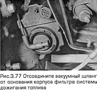
77. Raise the front and place it on supports. Disconnect the vacuum hose from the base of the filter housing (see fig.3.77).
78. Disconnect the negative battery cable (paragraph 1 chapter 5A).
79. Turn out bolts of a basic arm of the resonator from a forward crossbeam of engine compartment. Loosen the screws of the two clamps that secure the resonator to the hoses of the air mass meter and the intake air duct chamber. Then tilt the resonator away from the thermostat housing (chapter 4A).
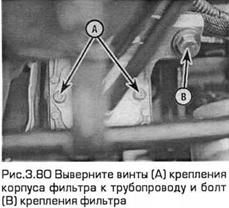
80. Remove the screws securing the filter housing to the pipeline. Turn out a fixing bolt. Then remove the case (see fig.3.80).
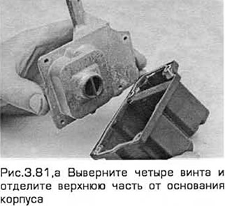
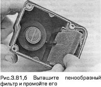
81. To disassemble the filter housing, remove the four screws and separate the top from the housing base. Take out the foam filter and wash it with a suitable solvent (see fig. 3.81, a, b). If any of the housing components are worn or damaged, the entire assembly must be replaced.
82. Installation - in the reverse order of removal.
Afterburner pipeline
Note: The filter housing and surrounding components become very hot when the engine is running. Wait until the engine has completely cooled down before starting work.
83. Disconnect the negative battery cable (paragraph 1 chapter 5).
84. Remove the air mass meter and resonator (chapter 4A).
85. Turn out bolts of a heat-insulating casing of a final collector. Detach the coolant hose so that the upper shroud can be removed. Lubricate the RVG pipeline nut and the nuts of the afterburning system with penetrating oil.
86. Remove the RVG pipeline (see above).
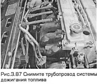
87. Remove the screws securing the filter housing to the pipeline (see fig.3.87). Turn out four nuts of fastening of the pipeline to a final collector. Remove the pipeline as a knot. Do not damage or bend it (see fig.3.87).
88. Thoroughly flush the pipeline, especially its threaded sections, as well as the threads in the manifold. Remove all traces of corrosion.
89. At installation carefully insert the pipeline into windows of a head of the block of cylinders. Apply anti-seize compound to the threads and tighten the flare nuts while holding each nozzle in its respective port. Tighten the nuts to the required torque.
90. Perform the remaining installation operations in the reverse order of removal.
Node - the filter housing of the fuel afterburning system together with the pipeline
Note: The filter housing and surrounding components become very hot when the engine is running. Wait until the engine has completely cooled down before starting work.
91. Disconnect the negative battery cable (paragraph 1 chapter 5A). Remove the resonator support bracket bolts from the engine compartment front cross member. Loosen the screws of the two clamps that secure the resonator to the hoses of the air mass meter and the intake air duct chamber. Then tilt the resonator away from the thermostat housing.
92. Drain the liquid from the cooling system (Chapter 1). Disconnect the coolant hose and coolant pipe/hose from the thermostat housing.
93. Turn out bolts of a heat-insulating casing of a final collector. Lubricate the RVG pipeline nut and the nuts of the afterburning system with penetrating oil.
94. Remove the RVG pipeline (see above).
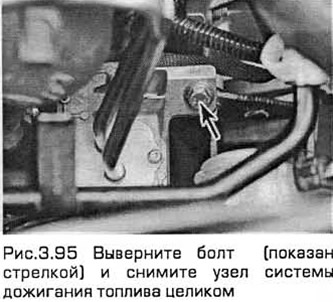
95. Turn out a bolt of fastening of the case of the filter. Turn out four nuts of fastening of branch pipes of the pipeline to a final collector. Remove the node. Do not damage or bend it (see fig.3.95).
96. Thoroughly flush the pipeline, especially its threaded sections, as well as the threads in the manifold. Remove all traces of corrosion.
97. At installation carefully insert the pipeline into windows of a head of the block of cylinders. Apply anti-seize compound to the threads and tighten the flare nuts while holding each nozzle in its respective port. Tighten the nuts to the required torque.
98. Perform the remaining installation operations in the reverse order of removal. Recharge the cooling system (Chapter 1). Start the engine and check for leaks from the exhaust system. After the engine has warmed up to normal operating temperature, check the coolant level.
Catalytic converter
Examination
99. Checking the operation of a catalytic converter requires complex, expensive equipment and, above all, a high-quality exhaust gas analyzer. If the level of carbon monoxide in the exhaust gases is too high, then a full test of the engine control system should be performed to eliminate all possible faults before declaring the converter defective. The car should be taken to dealers for inspection.
Replacement
100. On models with 4-cylinder engines, the catalytic converter is part of the exhaust pipe of the exhaust system. On V-6 models, the converters are part of the exhaust manifolds. Information related to its removal and installation is provided in chapter 4A.
Oxygen sensor
Examination
101. To check it, you need special diagnostic equipment connected to the sensor wiring. Make sure. that when the engine is running, the voltage changes from low to high. Do not attempt to test any parts without special equipment. Dealers must check.
Replacement
Note: This sensor is easily damaged. Therefore, you cannot drop it, you cannot knock on it. It will also not work if the supply wire is broken or flushed with solvent.
102. Disconnect the sensor connector (see fig.3.102).
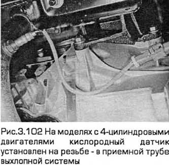
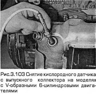
103. Raise the front and place it on supports. The sensor can then be removed while working under the vehicle. On models with 4-cylinder engines, unscrew the sensor from the exhaust pipe. On V-6 models, remove the sensors from both exhaust manifolds (see fig.3.103). Remove the seal (in the presence of).
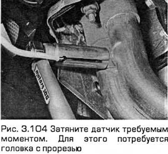
104. When installing, wash the sealing gasket, and if it is worn or damaged, replace it. Apply anti-seize compound to the sensor threads to keep them from sticking to the downpipe. Install the sensor, tighten it to the required torque. This will require a slotted head (see fig.3.104). Repair the wiring connection.
Visitor comments