Every 32,000 km or every 2 years.
1. On 4-cylinder models, the PCV valve is located at the front of the engine, under the exhaust manifold. On 6-cylinder models, the valve is located in a rubber hose connected to a pipe at the base of the intake manifold. See Chapter 4B for details.
2. Ensure that all system components are securely fastened, correctly positioned (no kinks or sharp bends that restrict flow), and in good condition. Replace any components that show signs of wear or damage.
3. The positive crankcase ventilation valve is designed to release gases from the crankcase. This creates a vacuum in the crankcase in most operating modes, especially at idle. Therefore, if the oil separator or positive crankcase ventilation valve is clogged, as you suspect, they must be replaced (Chapter 6). In this case, you can try to eliminate the clog by flushing with a suitable solvent. The positive crankcase ventilation valve should rattle when shaken.
4. If an oil leak is detected, disconnect the relevant pipes and hoses and make sure they are not clogged.
Models with 4-cylinder engine
5. Remove the air cleaner cover, air flow meter and resonator (if equipped). Make sure that the hose from the cylinder head cover to the air cleaner is not clogged or damaged.
6. Disconnect the T-shaped rubber tube from the fitting located on the left end of the intake manifold and from the metal crankcase breather located under the ignition coil. Attach a clean rubber hose to the breather. Draw air through the end of the hose, then blow into it. Air should pass freely in both directions.
7. You can check the intake manifold channels in the same way. When you blow air into it, you should hear it whistling out of the air duct chamber bell.
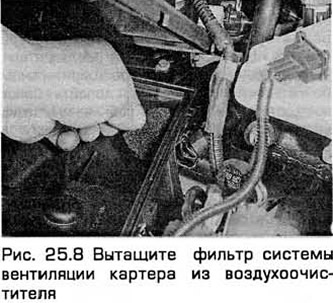
8. After removing the air filter (paragraph 24), clean the housing and remove the small foam filter from the right rear corner of the housing (see Fig. 25.8). If this filter is clogged with dirt or oil, it should be washed with a suitable solvent and dried before reinstallation.
Models with 6-cylinder engine
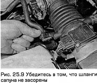
9. Disconnect the two breather hoses from the air duct connected to the air flow meter (see Fig. 25.9). Blow through each of them to check for blockages and damage.
10. Disconnect the short piece of rubber hose from the metal tube at the base of the intake manifold and check that the tube and hose are not clogged.
11. Disconnect the hose from the back of the positive air vent valve (this hose usually has a plastic casing) and make sure it is not clogged.
All models
12. Finally, securely fasten all removed components and wipe away any spilled oil.
(The text was obtained in its entirety from the specified website: FordBook.ru)