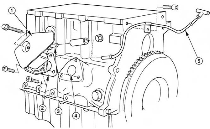
 Pic. 2.1a. Forced crankcase ventilation system.
1. Oil separator
2. Gasket
3. Crankcase ventilation valve
4. Hole in cylinder block/crankcase
5. Crankcase ventilation pipe and hoses
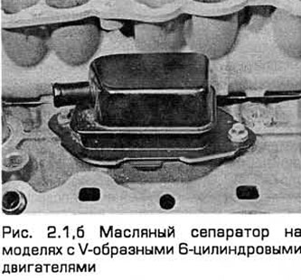
2. System components are designed to reduce the emission of unburned hydrocarbon particles from the crankcase, as well as to reduce the amount of oil sludge generated. Due to the vacuum created in the crankcase, in most operating modes (and especially at idle) oil vapors and gases that have broken through into the crankcase are sucked out of it. (This also forces air into the system.) Through the oil separator, these products enter the intake tract for subsequent combustion in the engine.
Fuel Evaporation Control System (WHALE)
3. This system is designed to reduce the level of penetration of unburned hydrocarbons into the atmosphere. For the concentration of gasoline vapors formed in the tank while the car is parked, a carbon adsorber is installed under the tank, and a sealed cap is installed on the fuel tank neck. While the engine is running, the vapors leave the adsorber through the purge valve, controlled by the BEU, into the intake tract for subsequent combustion in the engine.
4. During engine warm-up and/or idling, the purge valve does not open to prevent a rich mixture from entering the catalytic converter and to ensure normal engine operation. When the engine is warm and running at part load, the purge valve opens and closes intermittently to allow gasoline vapor to enter the intake tract.
Exhaust gas recirculation system (RVG)
5. To reduce the content of nitrogen oxides in the exhaust, part of the exhaust gases enters the intake manifold through the RVG valve. This lowers the combustion temperature.
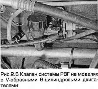
6. The system contains an RVG valve, an exhaust gas pressure difference sensor, an RVG solenoid valve, a BEU and various sensors. The EUU opens the RVG valve at the optimum moment for each operating mode. On models with V-shaped 6-cylinder engines, the valve of the RVG system is installed on the bulkhead of the engine compartment (see fig.2.6).
Fuel afterburning system
7. This system contains a valve "air injection", installed in the filter housing, valve solenoid, and pipeline. The system is designed to inject filtered air directly into the outlet ports. The intake of air from the filter housing by the engine is carried out due to the difference in pressure of the exhaust gases. The air flow enters the exhaust tract only if its pressure is below atmospheric pressure. To prevent exhaust gases from penetrating back into the filter, the valve "air injection" allows flow in only one direction.
8. The main task of the system is to increase the temperature of the exhaust gases at start-up so that the oxygen sensor and catalytic converter quickly warm up to operating temperature. Up to this point, the system reduces the emission of unburned hydrocarbons and carbon monoxide contained in the exhaust gases after combustion, due to the fact that a significant part of these substances burns in the manifold itself or in the catalytic converter.
9. The system operates only during engine warm-up, when the oxygen sensor does not affect the air-fuel ratio. The BEU controls the system through a solenoid valve.
Catalytic converter
10. The exhaust gases of a gasoline engine contain harmful substances: carbon monoxide, unburned hydrocarbons, nitrogen oxides, a small amount of a substance in the solid phase containing the smallest particles of lead.
11. These substances harm the environment.
12. A catalytic converter is designed to neutralize vehicle exhaust. It is installed in the exhaust system and contains noble metals - platinum, palladium or rhodium, which are catalysts that speed up the reaction between harmful emissions and oxygen. Carbon monoxide is oxidized to dioxide, and hydrocarbons are converted to water. In a three-phase catalytic converter, part of the nitrogen oxides is converted to nitrogen.
Note: The catalytic converter is not a filter. He also does not participate in a chemical reaction, but only accelerates it.
13. Converter contains element (cellular ceramic), coated with a composition of precious metals. It has a developed surface, washed by the flow of exhaust gases. The element is installed in a stainless steel case. A two-fraction catalytic converter performs a simple oxidation. It neutralizes only carbon monoxide and hydrocarbons. A three-fraction converter neutralizes carbon monoxide, hydrocarbons and nitrogen oxides. Three-fraction converters are divided into uncontrolled (no feedback), which neutralize from 50 to 70% of harmful substances, and controlled (with feedback), which neutralize over 90% of harmful substances.
14. The catalytic converter installed on the Ford-Mondeo vehicle shown in this manual is a three-way, controlled (with feedback).
Oxygen sensor
15. A sensor installed in the exhaust system provides the BEU with a continuous feedback signal. This allows you to adjust the composition of the mixture to ensure optimal operation of the catalytic converter.
16. The sensor has a built-in heating element controlled by the BEU, which allows you to quickly bring it to the operating temperature mode. The sensor tip is sensitive to oxygen. The sensor sends a voltage signal depending on the oxygen content in the exhaust gases. If the air-fuel mixture is too rich, the exhaust gases contain little oxygen, the sensor sends a low voltage signal. The voltage rises as the mixture leans and the amount of oxygen in the exhaust increases. Optimal conversion of the main constituents of the combustion products occurs when the air/fuel mixture ratio is maintained at a certain level, at which complete combustion of gasoline occurs. This ratio of components is called stoichiometric and corresponds to the ratio of air / fuel components (by weight) like 14.7:1. Near the critical point, the voltage output of the sensor changes abruptly. The ECU uses the signal change as a reference point and accordingly changes the air-fuel mixture ratio by changing the duration of the fuel injectors opening.
Exhaust gas differential pressure sensor
17. The sensor registers the difference in pressure of the exhaust gases at the narrowing of the pipeline of the exhaust gas recirculation system. It outputs a voltage signal to the BEU depending on the pressure difference.
Visitor comments