General description
1. The system is designed to prevent hydrocarbons from entering the atmosphere by capturing and concentrating fuel vapors from the carburetor fuel tank or fuel injection system.
2. The serviced components of the system include a container with charcoal and connecting pipes between the gas tank, the filler cap of the tank and the fuel injection system (see figure).
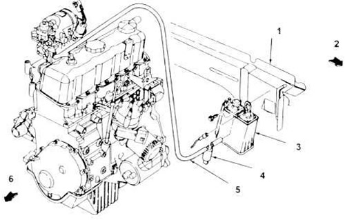
5.2, a. Typical ventilation system of the collection tank (four-cylinder engine).
1. Left lower frame guide.
2. Front of the car.
3. Capacity.
4. Cleaning solenoid.
5. Branch to PCV pipeline.
6. Front of the engine.
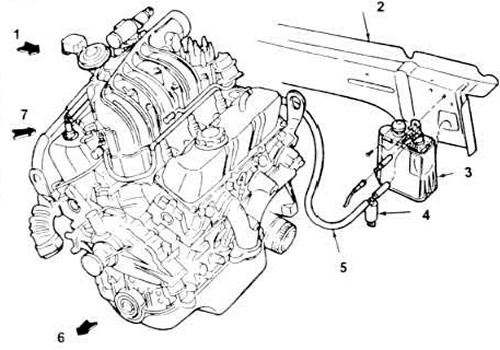
5.2, b. Typical ventilation system of a container collecting vapors (engine 3.0LV6 - 3.8LV6 is shown similarly).
1. Front part of the car.
2. Left lower frame guide.
3. Capacity.
4. Cleaning solenoid.
5. The supply hose runs above the transmission to the upper port of the PCV valve on the right timing cover.
6. Front of the engine.
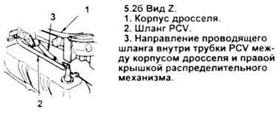
7. View Z.
3. The vapors trapped in the gas tank pass through a valve at the top of the tank. From the valve, the vapors leave through a pipeline and are fed to a container with carbon located between the left front wheel arch and the front bumper, where they accumulate until the next time the engine is turned on.
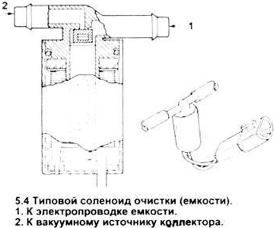
4. The outlet of the tank is connected to the housing cleaning solenoid, which is activated by an electrical signal (see figure); this solenoid, in turn, is connected to the air cleaner housing. Normally, the housing cleaning solenoid is in the closed position. When the engine is turned on, the solenoid receives a signal from the ECA, and it allows the intake vacuum to open the pipe between the tank and the air cleaner housing, as a result of which the vacuum removes the fuel vapors stored in the tank through the air cleaner into the engine, where they are burned.
Examination
Coal tank
5. There are no moving parts in the container, so there is nothing to wear out. Check for loose, cracked, broken or missing tips, and inspect the container itself for cracks and other damage. Replace a damaged container (see paragraph 9).
Tank purge solenoid valve
6. Remove the valve (see paragraph 13).
7. With the power to the valve disconnected, apply 5 inches of mercury to the vacuum source input (see Figure 5.4). The valve should not leak air. If it does, replace it.
8. Using additional wires, apply 9-14 volts to the valve electrical terminals. The valve should open and let air through. Otherwise, replace the valve.
Replacement of nodes
Coal tank
9. Locate the container in the engine compartment.
10. Locate and unscrew the only mounting bolt above the container (see figure).
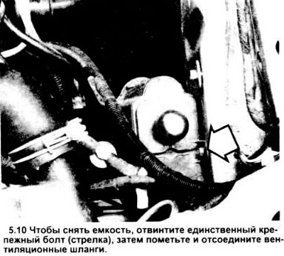
11. Lower the container, disconnect the hose from the cleaning valve or the cleaning solenoid valve, and remove the container.
12. Perform installation in reverse order.
All other elements
13. Referring to the vacuum supply hoses, valve diagrams in this section and the VECI label on your vehicle, locate the component requiring replacement.
[The original version can be found on the website: fordbook]