Contents: Graphic display lamps ↳ Fuel filler neck sensor ↳ Outside air temperature sensor ↳ Door switch ↳ Coolant level sensor ↳ Washer fluid reservoir level sensor ↳ Additional control system block ↳ Lamp performance control unit ↳ Vehicle Speed Control Switch ↳ Vacuum valve/switch ↳ Vacuum pump ↳ Vacuum drive ↳ PCB ↳ Heater Fan Motor ↳
Graphic display lamps
1. Remove the instrument cluster.
2. Remove the graphic display from the instrument cluster.
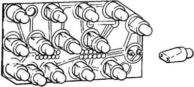
3. The lamps and LEDs can be removed from the graphic display unit with tweezers. When replacing the fuel filler warning LED, note that the mark on the LED must be aligned with the yellow spot on the panel.
Fuel filler neck sensor
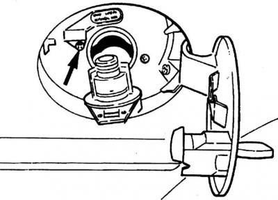
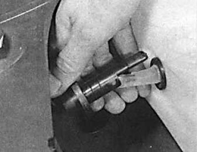
The sensor is indicated by the arrow.
1. Open the fuel filler cap and remove the filler plug.
2. In the luggage compartment, remove the trim on the right side and disconnect the sensor connector.
3. Unscrew the screw securing the sensor to the neck of the filler neck.
4. Remove the sensor.
5. The sensor is installed in the reverse order of removal.
Outside air temperature sensor
The sensor is located under the front bumper.
1. Disconnect the electrical connector from the sensor.
2. Press the fixing clamps into the sensor and remove the sensor (indicated by the arrow).
3. When installing, first connect the connector, then insert the hook on the end of the sensor into the slot and press the sensor into place, then secure the connector into the clamp.
Door switch
1. Remove the inner door trim.
2. Pull the switch outward to release it from the lock and disconnect the connector.
3. The door switch is installed in the reverse order of removal.
Coolant level sensor
1. Remove the cap from the expansion tank.
2. Drain the coolant from the tank until the sensor is above the liquid level.
3. Disconnect the electrical connector.
4. Unscrew the fastening ring and remove the sensor from the socket, while marking the location of the chamfers on the seal and the sensor.
5. The sensor is installed in the reverse order of removal.
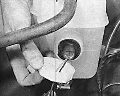
Washer fluid reservoir level sensor
1. Drain the liquid from the tank until the sensor is above the liquid level.
2. Disconnect the electrical connector.
3. Carefully lift the sensor and remove it from the seal, noting the location of the chamfers on the seal and sensor.
4. The sensor is installed in the reverse order of removal.
Additional control system block
1. Remove the instrument cluster and the upper part of the panel.
Models before April 1992.
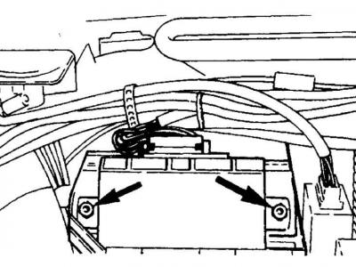
2. Unscrew the two screws (indicated by arrows) securing the unit, disconnect the connector, having first pressed the locking clamp, and remove the unit.
3. Installation is carried out in the reverse order of removal.
4. Before installing the panel, check the functionality of the additional control system.
Models since April 1992.
5. Remove the trim from the hood release lever to access the mounting screws.
6. Unscrew the three screws and remove the lever.
7. Disconnect the hood release cable mounting brackets and disconnect the cable from the lever.
8. Unscrew the five screws securing the lower instrument panel trim and remove it.
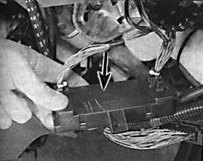
9. Unscrew the block mounting screw, remove the connector from the block and remove the block (indicated by the arrow) from the car.
10. Installation is carried out in the reverse order of removal.
Lamp performance control unit
Incandescent lamp performance control unit
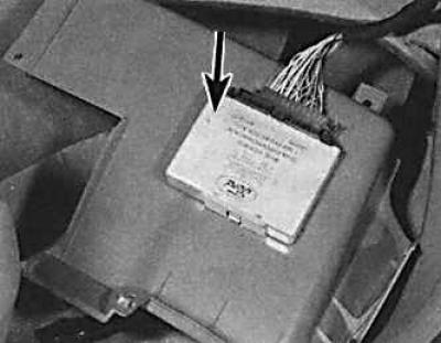
The block is indicated by an arrow.
On models from April 1992, the incandescent lamp control unit is located on the right above the pedals.
Models before April 1992.
1. Remove the trim under the instrument panel on the driver's side, which is secured with six screws, one of which is only accessible after removing the fan grille.
2. Remove the unit from the bracket, disconnect the connector, having first pressed the locking clamp, and remove the unit.
3. Installation is carried out in the reverse order of removal.
Models since April 1992.
4. Remove the trim under the instrument panel on the driver's side.
5. Remove the unit from the bracket, disconnect the connector, having first pressed the locking clamp, and remove the unit.
6. Installation is carried out in the reverse order of removal.
Vehicle Speed Control Switch
1. Remove the steering wheel.
2. Unscrew the three screws securing the horn contact bracket.
3. Disconnect the wires and remove the bracket.
4. Carefully remove the switch from the steering wheel.
Vacuum valve/switch
The clutch pedal switch is mounted in a spring suspension to compensate for minor deviations in pedal position during operation of the self-adjusting mechanism.
1. Remove the trim under the instrument panel on the driver's side.
2. On the brake pedal, loosen the upper switch and the lower mounting nut, then unscrew the nut completely.
3. Disconnect the wire contact and vacuum hose from the valve, remove the valve.
4. Disconnect the wire connector and vacuum hose, then remove the clutch pedal switch from the suspension.
5. Installation is carried out in the reverse order of removal.
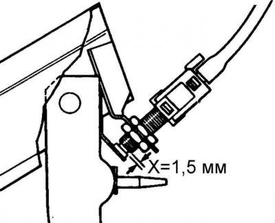
6. Adjust the position of the switch so that there is a gap X = at least 1.5 mm between the switch stem head and the switch body.
Vacuum pump
The vacuum pump is located behind the left headlight on carbureted models and behind the right headlight on all fuel-injected models.
1. Remove the corresponding headlight.
2. Disconnect the multi-plug and vacuum hose from the pump.
3. Using the lever, release the three supports and remove the pump.
4. When installing the pump in place, insert the pump supports with pliers.
5. Connect the vacuum hose and multi-pin connector, then install the headlight.
Vacuum drive
1. Disconnect one end of the vacuum actuator-throttle cable.
2. Disconnect the vacuum hose from the drive.
3. Unscrew the drive lock nut and remove the vacuum drive from the suspension.
4. Installation is carried out in the reverse order of removal.
5. On all models except the 2.0 dm³ carburetor, adjust the cable so that it hangs slightly at the idle throttle position.
6. On all models except the 2.0 dm³ carburetor, adjust the cable so that it hangs slightly at the idle throttle position.
7. Observe the plunger of the stepper motor. Turn on the ignition for a few seconds, then turn it off again. When the ignition is off, the plunger should be in the "fully open" position, i.e. pulled in.
8. After retracting the plunger, disconnect the ground wire from the battery.
9. Adjust the vacuum cable so that it has a slight sag, then connect the ground wire to the battery.
PCB
The printed circuit board is located in the steering wheel and can be removed after separating the horn contact plate and disconnecting the switch leads.
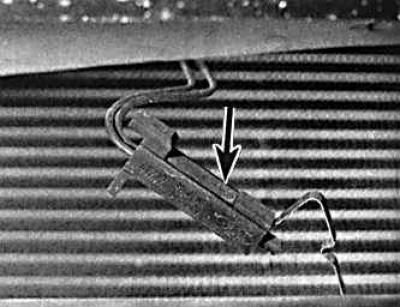
Heater Fan Motor
1. Remove the negative cable from the battery.
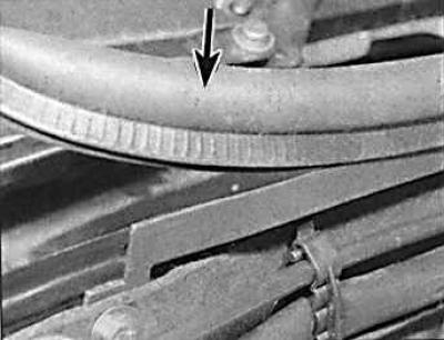
2. Remove the rubber seal (indicated by the arrow) from the top of the engine compartment bulkhead.
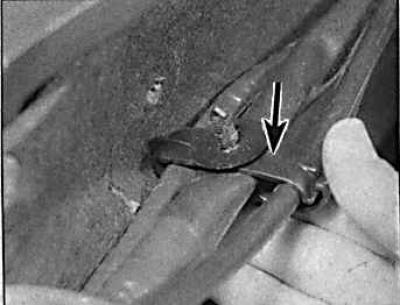
3. Remove the two wire fastening brackets (arrow) from the front of the partition.
4. Unscrew the two screws and remove the two brackets that secure the camera cover (arrow). Remove the cover.
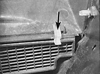
5. Disconnect the multi-pin connector from the blower motor resistor and the ground bus.
6. Unscrew the two bolts securing the heater fan motor. Remove the motor together with the casing and resistor.
7. Remove the fan housing halves retaining clips and remove the engine.
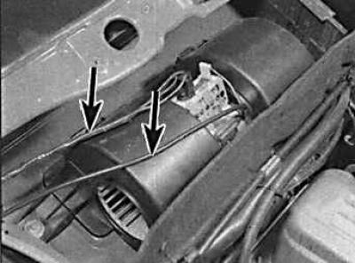
8. Installation is performed in the reverse order of removal. Connect the wires (indicated by arrows) connecting the fan motor.
The original version can be found on the website: www.FordBook.ru