Only for heater or heating - air conditioning systems with mechanical control
Note: This procedure is only carried out on vehicles with a heater (without air conditioning) and on vehicles with a mechanically controlled heating and air conditioning system. If your vehicle is equipped with an electronic automatic temperature control system (EATL), see section 16.
1. Disconnect the negative cable from the battery.
2. Remove the dashboard trim (see chapter 11).
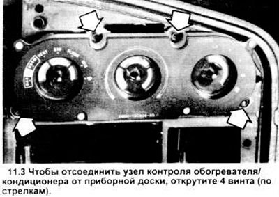
3. Unscrew the 4 screws connecting the control unit to the dashboard (see picture).
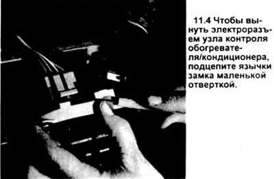
4. Pull the control unit out of the dashboard opening and pull out the electrical connectors (see picture).
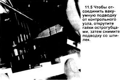
5. Unscrew the nuts securing the vacuum connection from the stand (see picture), disconnect the vacuum connection from the control unit.
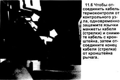
6. Disconnect the temperature control cable from the control node (see picture).
7. Reassemble in reverse order. Be sure to put new nuts on the connection of the vacuum connection to the control unit.
Caution: the vacuum connection nuts push in, do not try to screw them onto the stand.
Blower switch
8. Disconnect the negative battery cable.
9. Remove the fan switch button from the switch plate by pulling it out towards you.
10. Unscrew the control assembly from the dashboard (see above) and pull it out so that you can work with the blower switch.
11. Pull out the electrical connectors from the switch.
12. If the car is not equipped with air conditioning, unscrew the screw connecting the switch to the control node and located below the control node.
13. On vehicles equipped with air conditioning, this screw is located behind the control assembly.
14 Remove the switch.
15. Assembly is carried out in the reverse order.
Electronic automatic temperature control system (EATL)
Note: Testing of the EATL system is outside the scope of this publication.
Control Node
16. Disconnect the negative battery cable.
17. Pull out the bottom left and right dashboard snap-in trims. Remove the eight screws securing the top trim panel (see chapter 11).
18. Pull the bottom edge of the top trim panel out of the dashboard. It is best to pick it up by the lower left corner and take it out, moving your hands around the perimeter clockwise.
19. Unscrew the four screws (they may have torx sockets that require a special tool), fixing the control head (see picture). Remove the control head from the dashboard and place it so that you have access to the rear connectors.
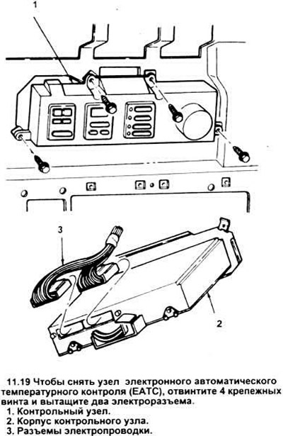
20. Disconnect the 2 electrical connectors from the control node.
21. Unscrew 2 nuts securing the vacuum connection. Pull the control node out of the toolbox.
22. Assembly is carried out in the reverse order.
The backlight lamp of the liquid crystal indicator (LCD) control node
Note: This procedure allows you to change the light bulb of the LCD display, it has nothing to do with backlight bulbs or indicator bulbs (LED). If the main lamps of the control node do not work, it must be replaced.
23. Remove the control unit from the vehicle (see above).
24. Put it on a clean piece of cardboard.
25. Unscrew the two screws on the back of the case that secure the top cover (see picture).
26. Lift the cover. Do not turn the module upside down.
Warning: do not touch the circuit elements and wires on the board. You may well have a supply of static electricity sufficient to ground and damage them upon contact. Also be careful with the rubber cable running from the switch assembly to the board - don't kink it.
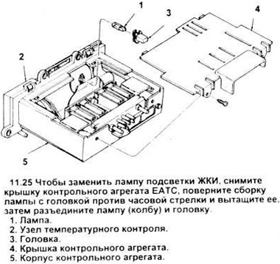
27. Protruding from the back of the switch assembly are a gray rectangular plastic bulb and its head assembly (see figure 11.25). To remove them, you need to carefully turn them counterclockwise with small pliers, without touching other parts. After moving the head of the flask out of place with pliers, carry out further rotation by hand, approximately 45 degrees. After that, pull the head of the flask out of the switch body.
28. Pull the old flask out of the socket, install a new flask instead (number D4AZ - 13466 - A, trade number 37) into the nest.
29. Place bulb with head assembly into switch body and rotate 45 degrees clockwise until head snaps into place. Do not use pliers when installing the head.
30. Subsequent assembly is carried out in the reverse order of disassembly.
Solar sensor assembly
31. Disconnect the negative cable from the battery.
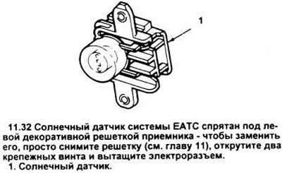
32. Remove the left decorative grille of the radio (see chapter 11) and remove the sun sensor assembly (see picture) with two studs holding it.
33. Pull out the electrical connector of the solar sensor.
34. Installation is carried out in the reverse order.
Internal Sensor Assembly
35. Disconnect the negative battery cable.
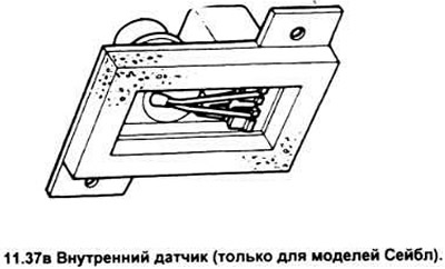
36. In Tauras vehicles, remove the right trim panel assembly (see chapter 11). In Sable, lower the glove box compartment down by depressing the locks holding it.
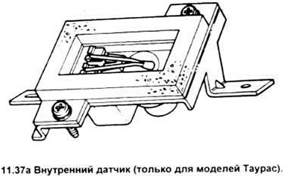
37. Unscrew the two mounting screws of the sensor assembly (see picture).
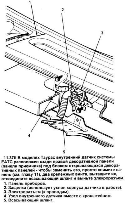
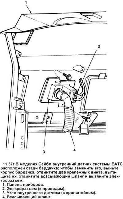
38. Pull out the electrical connector of the internal sensor.
39. Carefully opening the latch, disconnect the suction hose from the internal sensor.
40. Installation of a new sensor is carried out in the reverse order.
External Sensor Assembly
41. Disconnect the negative battery cable.
42. Open the hood and locate the external sensor assembly. It is mounted in front of the condenser on a bracket (see picture).

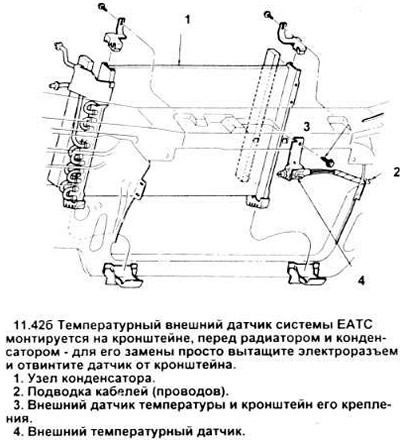
43. Unscrew a nut of fastening of the external gauge and remove the gauge.
44. Disconnect the electrical connector from the sensor.
45. Install in reverse order.
Visitor comments