Engine and Fan Assembly
1. Open the glove compartment door, release its latches, and lower the door down.
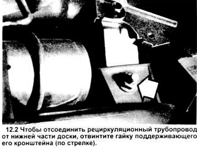
2. Unscrew the nut securing the recirculation pipe bracket to the hood (see figure).
3. Disconnect the vacuum connector from the recirculation vacuum motor inlet.
4. Remove the 6 screws securing the recirculation pipe to the heater/evaporator assembly (see illustration).
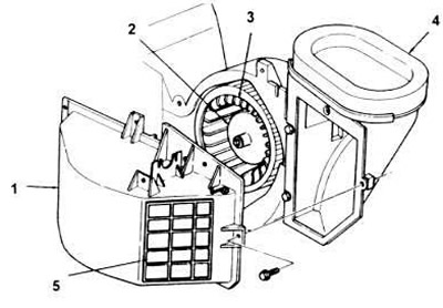
12.4. Three-dimensional image of the recirculation pipeline and fan motor in the housing.
1. Recirculation pipeline.
2. Motor.
3. Fan.
4. External air intake.
5. Recirculator door.
5. Disconnect the heater unit from the recirculation pipe. Lower the latter into the gap between the instrument panel and the heater housing.
6. Disconnect the fan motor electrical connector from the wiring system.
7. Remove the fan bracket and the fan itself (see figure).
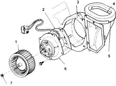
12.7. Three-dimensional image of the fan, motor and housing unit.
1. Fan.
2. Gasket.
3. Motor housing (integral with the heater unit housing).
4. External air intake.
5. Air intake gasket.
6. Motor
7. Locking washer.
8. Unscrew the 4 screws from the motor support plate. Remove the motor from the housing.
9. Perform installation in reverse order.
Fan motor resistance
10. Disconnect the negative cable from the battery.
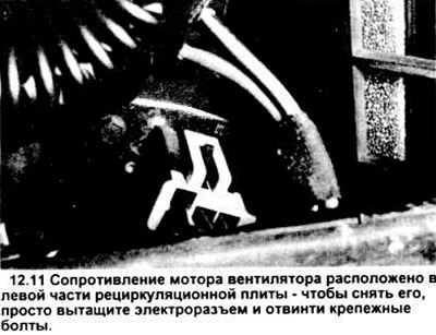
11. To access the fan motor resistor and the thermal limiter, open the glove compartment door, release the glove compartment housing clamps and lower it down. The fan motor resistor and the thermal limiter are mounted on the heater housing (see figure), to the left of the recirculation pipe.
12. Remove the electrical connector of the resistor.
13. Unscrew the two screws securing the resistor and remove it from the heater body.
14. Installation is carried out in reverse order.
Caution: Do not apply sealant to the mounting surface of the resistor.
The original source of this article can be found at: www.FordBook.ru