Main components of the heater:
- a heater heat exchanger (radiator) designed to heat the air entering the passenger compartment with the heat of the engine cooling liquid;
- an electrically driven fan (blower) that provides a controlled supply of outside air to the heater and air conditioner flaps;
- flap for regulating the temperature of air coming from the heater into the passenger compartment; the amount of air passing through the heater's heat exchanger and outside air bypassing the heat exchanger depends on the change in its position;
- flaps for distributing air coming from the heater through air ducts into the passenger compartment or for blowing air onto the windshield.
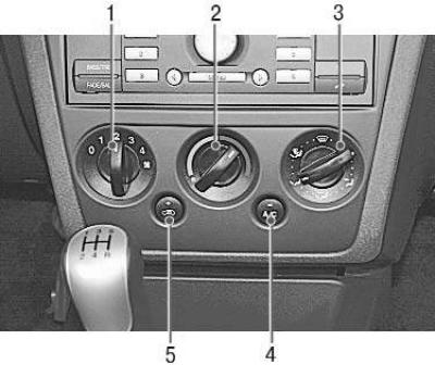
Fig. 11.2. Control panel of the heating (air conditioning) and ventilation system of the passenger compartment: 1 – air blower fan operating mode switch; 2 – regulator of the temperature of the air entering the passenger compartment; 3 – air flow distribution regulator; 4 – air conditioner switch; 5 – recirculation mode switch
Fig. 11.2 shows the control panel of the heating (air conditioning) and ventilation unit of the car interior, installed on the console of the instrument panel. The purpose and operation of the air conditioner controls are described in Section. "The structure of the car" (cm. "Heating (air conditioning) and ventilation of the passenger compartment").
Switch 1 of the air blower fan modes operates independently of the position of the air distribution and temperature regulators and controls the fan speed by changing the voltage in the power supply circuit of the electric motor.
The air flow distribution regulator 3 and the temperature regulator 2 control the heater flaps using a cable drive.
The air conditioning system is controlled by controls located on the panel shared with the heater (see Fig. 11.2).
The air conditioning system includes the following elements.
Compressor is driven by a belt from the engine crankshaft pulley. A friction electromagnetic clutch is built into the compressor pulley, disconnecting the compressor shaft from the pulley or connecting them when the air conditioner is running, based on a signal from the engine's electronic control unit. When operating, the compressor compresses the refrigerant vapors coming from the evaporator heat exchanger to high pressure. The temperature of the refrigerant vapors at the compressor outlet is significantly higher than at the inlet.
Pressure reducing valve is built into the compressor and performs a protective function, triggering when the pressure increases above the permissible value at the compressor outlet. The reason for the operation of the pressure reducing valve may be the failure of the high-pressure valve, electric fan, etc.
Heat exchanger (radiator) of the condenser is located in front of the engine cooling system radiator and has a developed ribbon core insert for rapid cooling and condensation of refrigerant vapors compressed by the compressor to high pressure.
Throttle body (reducer) with mesh filters at the inlet and outlet is installed in the pipeline supplying liquid refrigerant to the evaporator heat exchanger. The throttle hole in the pipe limits the flow of liquid refrigerant and reduces the pressure in the evaporator. After the engine stops, the liquid refrigerant continues to flow for some time through the throttle pipe from the high-pressure zone to the low-pressure zone. The flow of liquid through the throttle hole is accompanied by a characteristic hissing sound, which can be heard for 30-60 seconds after the engine stops and does not indicate a malfunction.
Evaporator heat exchanger (radiator). The liquid coolant of the condenser heat exchanger enters the evaporator heat exchanger located in the heater unit through the throttle pipe. In the heat exchanger, the liquid passes into a gaseous state, absorbing heat. The moisture contained in the air entering the heat exchanger condenses on it, flows down from the evaporator and is removed from the heater unit. From the evaporator heat exchanger, the gaseous coolant with an admixture of a small amount of the liquid fraction of the coolant and drops of refrigeration oil enters the receiver, which is connected to the outlet pipeline of the evaporator.
Receiver-dryer. In the lower part of the receiver body there is a container with an absorber of water vapor from the refrigerant vapors, which, freed from moisture through a special hole in the intake tube, mix with refrigeration oil. In the upper part of the receiver body there are fittings for connecting pipelines. The receiver is not repairable, it must be replaced only in assembly.
In addition to the listed elements, the system includes high and low pressure valves, as well as pressure sensors.
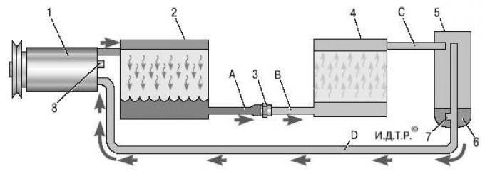
Fig. 11.3. Schematic diagram of the movement of refrigerant in the air conditioning system: 1 – air conditioning compressor; 2 – condenser heat exchanger; 3 – throttle pipe (reducer); 4 – evaporator heat exchanger; 5 – receiver-dryer; 6 – moisture absorber in the receiver; 7 – hole for mixing refrigerant vapors with refrigeration oil; 8 – pressure reducing valve in the compressor; A – liquid refrigerant under high pressure; B – liquid refrigerant under low pressure; C – high pressure gaseous refrigerant; D – low pressure gaseous refrigerant
The basic diagram of the movement of refrigerant in the air conditioning system is shown in Fig. 11.3.
Attention! All repair work on the air conditioning system should be performed only when the system is completely discharged.
Warning: Since refrigerant vapors are toxic, repair the system using special equipment available at specialized air conditioning service centers.
Note. Due to the specific features of air conditioning system repair (see warnings above), this subsection describes only the work on removing and installing the control unit for the heating (air conditioning) and ventilation system and replacing the filter for the air entering the cabin, since removing other elements of the heating and air conditioning unit (including the heater radiator) requires complete removal of the unit from the vehicle with depressurization of the air conditioning system.
[For details, please visit the website: FORDBOOK.ru]