


1. Disconnect the wire from the negative terminal of the battery.
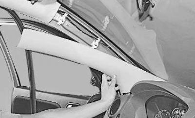
2. Remove the front pillar trims (see "Removal and installation of interior trim").
3. Remove the steering wheel (see "Removal and installation the steering wheel").
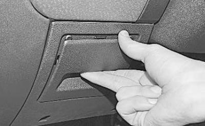
4. Open the small items drawer…
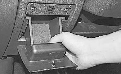
5. …lift it up…
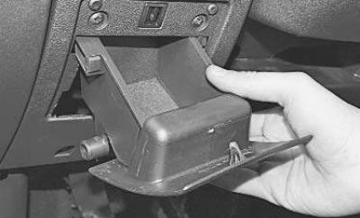
6. …and remove it.
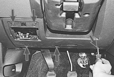
7. Remove the five mounting screws…
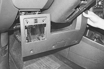
8. …and remove the cover.
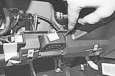
9. Press the clamps…
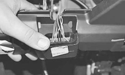
10. …move the clamp down…
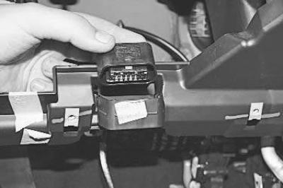
11. …and remove the diagnostic connector.
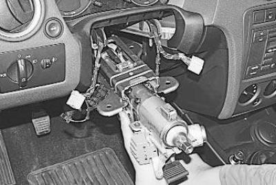
12. Remove the steering column (see "Removal and installation the steering column").
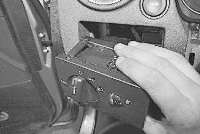
13. Remove the exterior lighting control unit (see "Replacing the external lighting control unit").
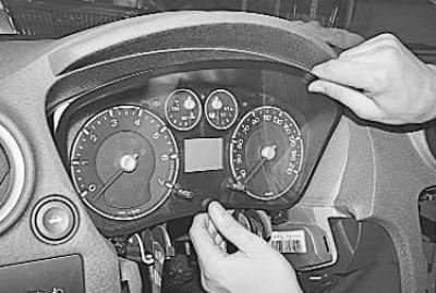
14. Remove the instrument cluster (see "Removal and installation the instrument cluster")…
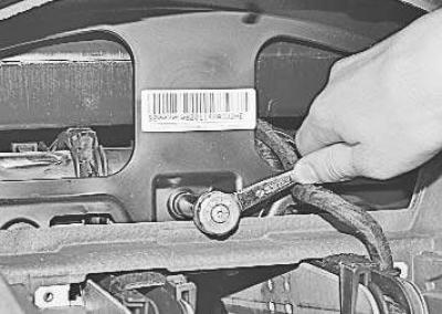
15. …and unscrew the bolt securing the instrument panel to the frame.
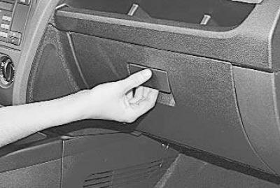
16. Open the glove compartment…
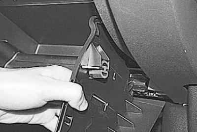
17. ...pressing the walls of the glove compartment with your fingers on both sides, move the travel limiters...
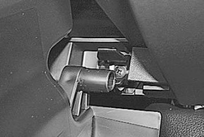
18. …remove the hinge axle from the bracket…
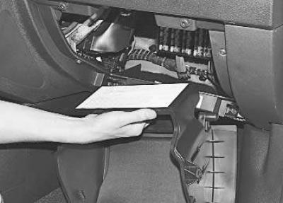
19. …and remove the glove box.
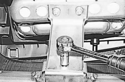
20. Unscrew the three nuts and remove the bracket.
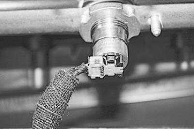
21. Disconnect the wiring harness connector from the front passenger airbag terminal.
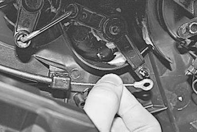
22. Remove the cable end from the air temperature regulator flap drive shaft…
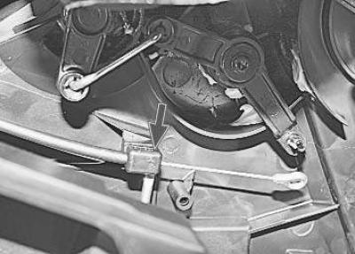
23. …and disconnect the cable sheath holder from the heater body.
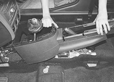
24. Remove the floor tunnel lining (see "Removal and installation the floor tunnel lining").
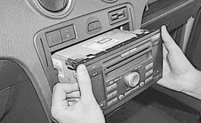
25. Remove the car radio from the center console of the instrument panel (see "Removal and installation a car radio").
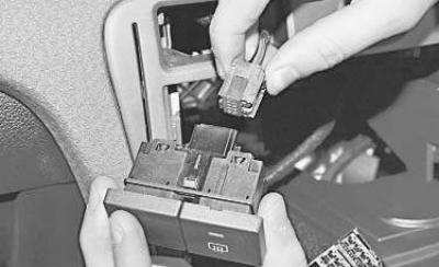
26. Remove the switch block...
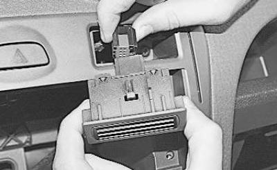
27. …and the coin holder (see "Replacing the instrument panel switches").
Note: Depending on the equipment, the coin holder may be replaced by an electronic stability program (ESP) switch or an airbag deactivation indicator lamp.
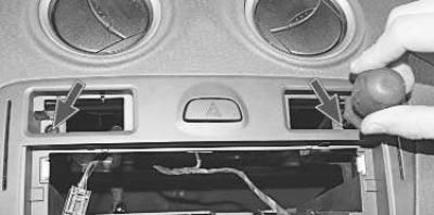
28. Remove the two screws securing the upper panel to the center console…
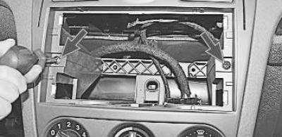
29. …two screws of the middle mount…
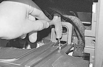
30. …and one internal mounting screw.
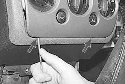
31. Carefully pry up the center console panel with a screwdriver…
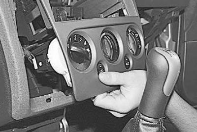
32. …and, overcoming the resistance of the metal clamps, move the panel away.
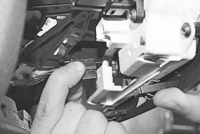
33. Disconnect the wiring harness connector from the terminal of the heating (air conditioning) and ventilation control unit.
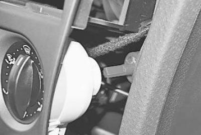
34. Disconnect the cable end from the blower mode switch…
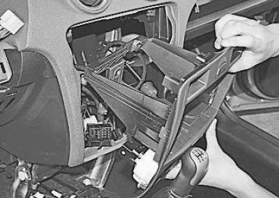
35. …and remove the center console trim assembly with the heating (air conditioning) and ventilation control unit.
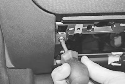
36. Remove one screw securing the left trim to the instrument panel…
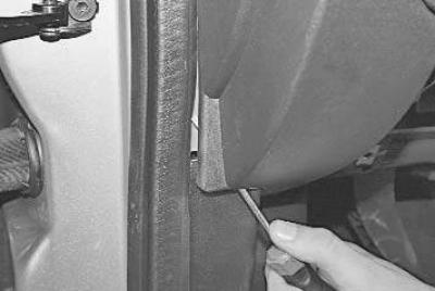
37. …pry up the plastic retainer of the lower lining mount with a screwdriver…
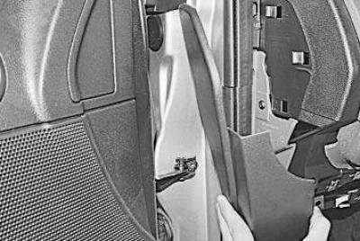
38. …and remove the trim by releasing its latches from the holders on the instrument panel.
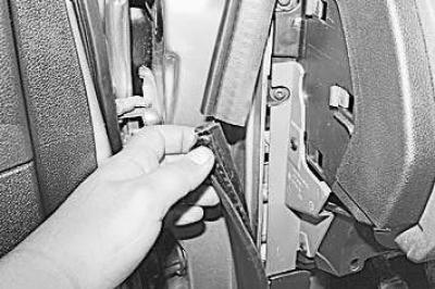
39. Remove the rubber door opening seals and set them aside.
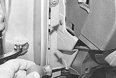
40. Remove the two screws securing the protective cover…
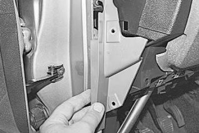
41. …and take it off.
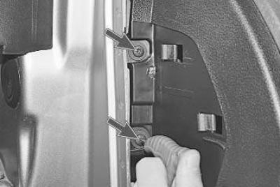
42. Remove two screws…
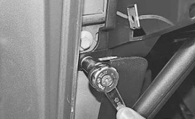
43. …and one bolt on the left side of the instrument panel mount to the front pillar.
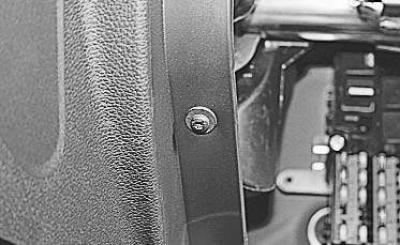
44. Remove one screw on the left side of the glove box frame mount to the instrument panel frame.
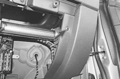
45. Remove the screw securing the right instrument panel trim and disassemble the right side of the instrument panel (see similar operations in paragraphs 36–43).

46. Remove one screw on the right side of the instrument panel mounting to the panel frame.
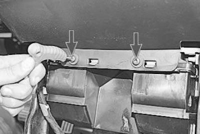
47. Remove the two lower screws securing the instrument panel to the frame…
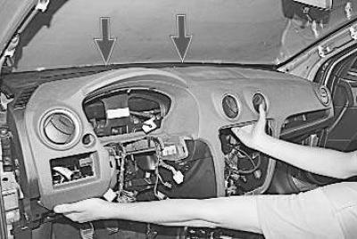
48. …and remove the decorative panel, overcoming the resistance of the plastic clips.
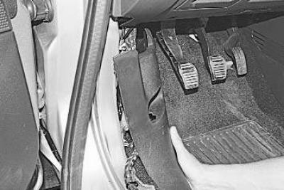
49. Remove the left and right front door sill trims (see "Removal and installation of interior trim").
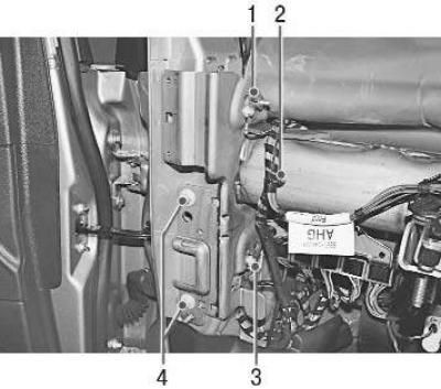
50. Unscrew bolts 1 and 3 securing the ground wires to the instrument panel frame. Remove holder 2 of the wire harness and move the harness aside. Unscrew two bolts 4 on the left and right sides securing the side of the instrument panel frame to the front pillar…
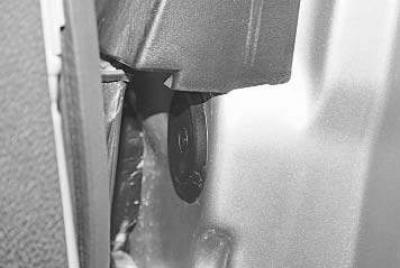
51. … remove the plug and unscrew the inner bolt of the side fastening of the instrument panel frame to the left front pillar of the body.
52. Similarly, unscrew the frame mounting bolt on the right side.
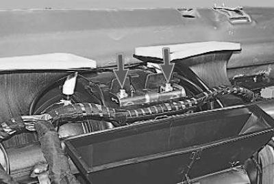
53. Remove the two upper bolts securing the instrument panel frame to the heater body.
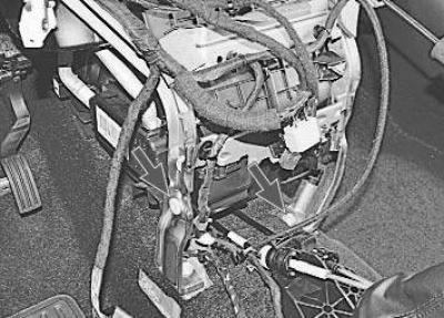
54. Disconnect all wiring harness holders from the instrument panel frame. Unscrew the two central bolts securing the panel frame to the body base and remove it from the gap between the pillars.
55. Install all removed parts in the reverse order of removal.