1. Disconnect the wire from the negative terminal of the battery.
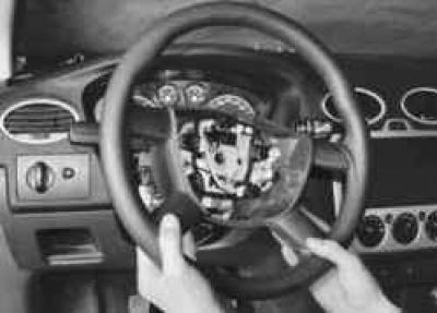
2. Remove the steering wheel (see "Removing and installing the steering wheel").
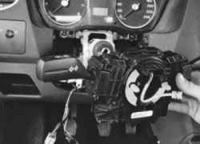
3. Remove the steering column switches assembly with the connector (see "Replacing the steering column switches").
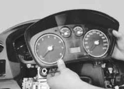
4. Remove the instrument cluster (see "Removing and installing the instrument cluster").
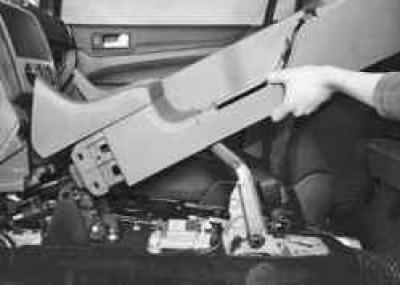
5. Remove the floor tunnel lining (see "Removing and installing the floor tunnel lining").
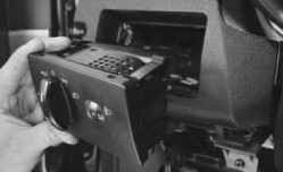
6. Remove the exterior lighting control unit (see "Removing and installing the exterior lighting control unit").
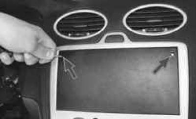
7. Through the two holes in the plug of the socket for installing the radio, press the clamps..

8. …and remove the plug.
NOTE: If your vehicle has a radio, remove it.
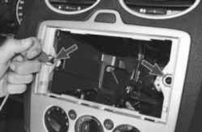
9. Remove the two screws securing the central trim…
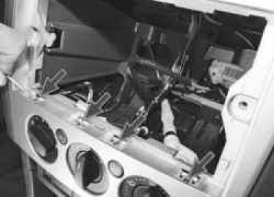
10. …push the four fasteners upwards with a screwdriver…
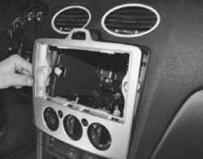
11. …and remove the center trim.
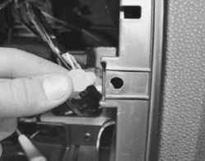
NOTE: Replace plastic cage nuts with damaged threads.
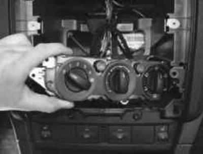
12. Remove the heating (air conditioning) and ventilation control unit (see "Removing and installing the heating (air conditioning) and ventilation control unit").
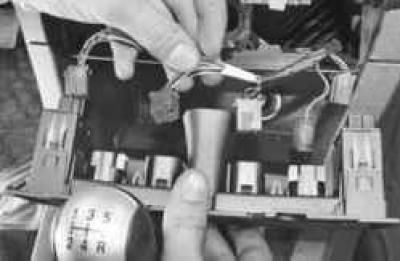
13. Remove the switch block (see "Replacing the Instrument Panel Switches").
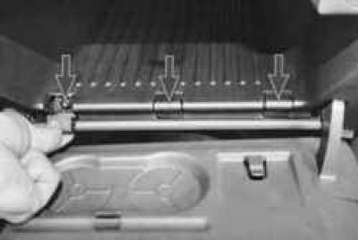
14. Open the glove compartment lid and remove the decorative caps of the three lower screws that secure it.
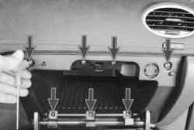
15. Remove the seven screws securing the glove box to the instrument panel…
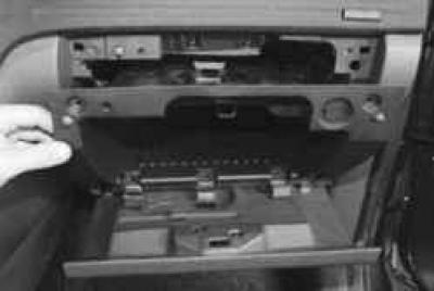
16. …and remove the box.
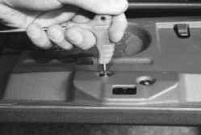
17. If necessary, remove the two screws securing the glove compartment lid lock…
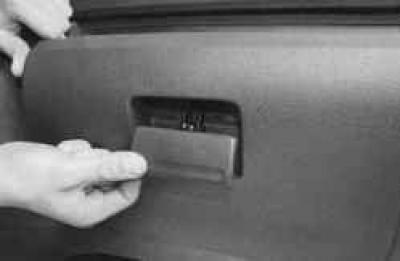
18. …and remove the lock.
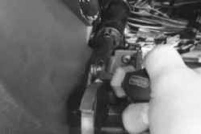
19. Pry it off with a screwdriver..
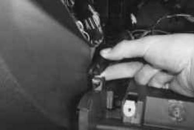
20. …remove the tip of the pneumatic stop rod from the pin of the left lever of the glove compartment lid…
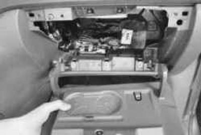
21. …and remove the glove compartment cover by removing its levers from the grooves of the instrument panel.
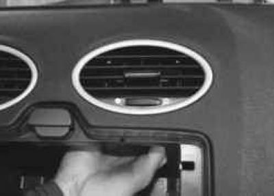
22. From the inside of the instrument panel, press outwards…
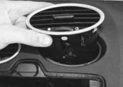
23. …and remove the two central and two side nozzles of the heating (air conditioning) and ventilation system. All four nozzles are removed using the same techniques.
NOTE: Removal of the nozzles is necessary to gain access to the instrument panel mounting points.
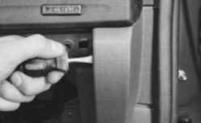
24. Pry it off with a screwdriver..
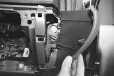
25. …remove the right instrument panel trim.
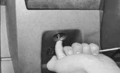
26. Remove the screw securing the left instrument panel trim…
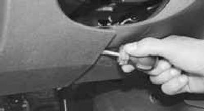
27. …and, prying it with a screwdriver…
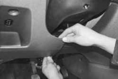
28. …detach the edge of the left trim from the instrument panel…
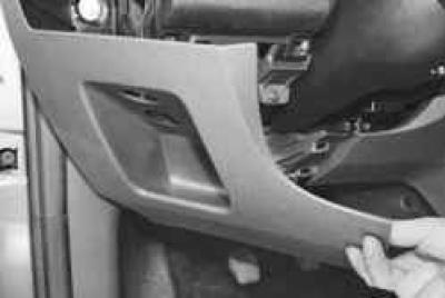
29. …move the overlay down…
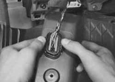
30. …from the back of the cover, release the clamps of the diagnostic connector…
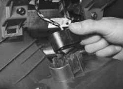
31. …remove the connector from the cover hole and remove the cover.
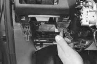
32. Remove the two screws securing the decorative panel to the instrument panel frame at the bottom left…
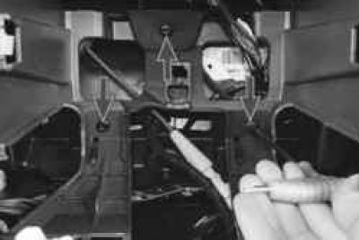
33. …three screws in the center, in the slot under the radio…
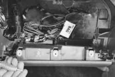
34. …two screws at the bottom right…
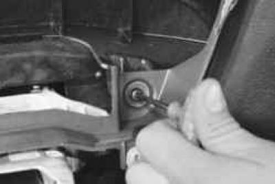
35. …screw in the opening for the instrument cluster…
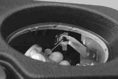
36. …screw at the top right…
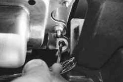
37. …and the screw at the bottom right.
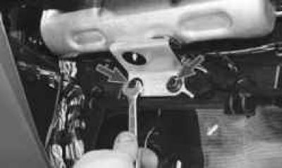
38. Remove the two bolts securing the decorative panel to the instrument panel frame…
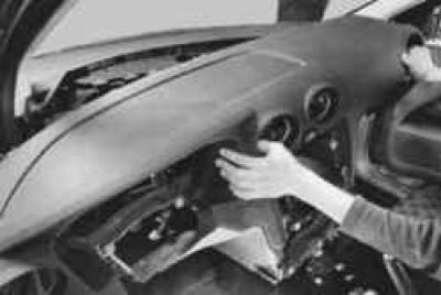
39. …and remove the decorative panel, disconnecting the wire harness holders from its inner side.
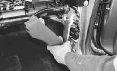
40. Remove the right and left front sill trims (see "Removing and installing interior trim").
41. Remove the steering column (see "Removing and installing the steering column").
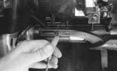
42. Remove the screw securing the left air duct to the instrument panel frame…
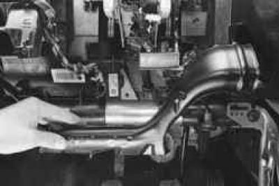
43. …and remove the air duct.
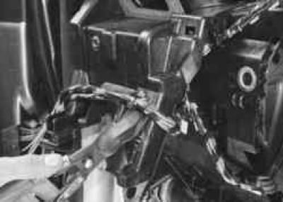
44. Disconnect the wire harness holders from the left instrument panel frame bracket…
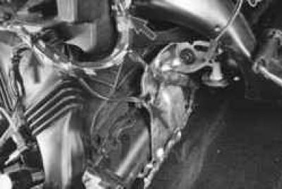
45. …from the central air duct, right instrument panel support bracket…
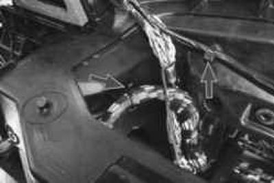
46. …and from the upper air duct.
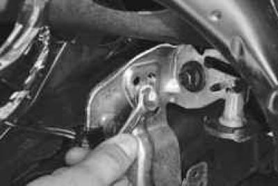
47. Remove the bolt securing the ground wire to the right instrument panel support bracket…
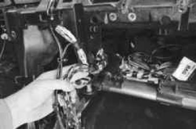
48. …pull the wire harness out of the instrument panel frame…
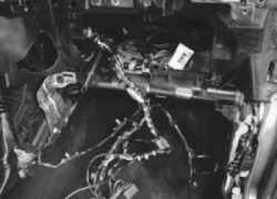
49. …and place it on the floor of the truck body.
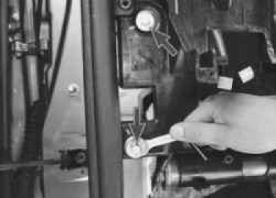
50. Remove the two bolts securing the left instrument panel frame bracket to the left front pillar.
51. Unscrew two similar bolts securing the right bracket of the instrument panel frame to the right front pillar, located symmetrically relative to the longitudinal axis of the vehicle.
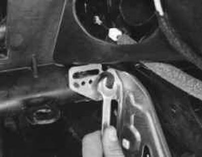
52. Remove the bolt securing the left support bracket to the instrument panel frame…
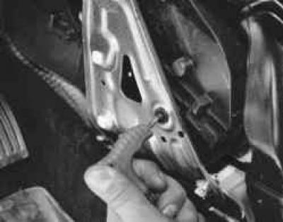
53. … screw for fastening to the heater housing support bracket…
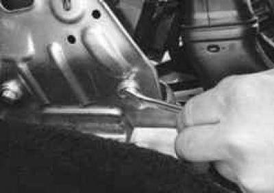
54. …two bolts securing the support bracket to the body base…
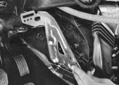
55. …and remove the bracket.
56. Remove the right support bracket in the same way.
NOTE: The difference between the right support bracket and the left one is that the heater housing is not attached to it.
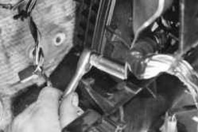
57. Remove the two bolts securing the instrument panel frame to the steering column mounting bracket.
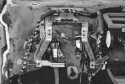
NOTE: The instrument panel frame mounting bolts to the steering column mounting bracket pass through two holes in the bracket, shown by arrows in the photo.
58. Remove both front doors (see "Removing and installing the front door").
NOTE: It is necessary to remove the front doors because the side bolts that secure the instrument panel frame to the A-pillars are not accessible when the doors are installed.
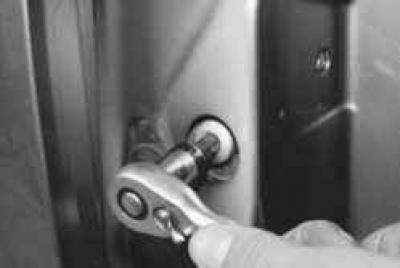
59. Unscrew one bolt of the side fastening of the instrument panel frame to the left and right front pillars of the body…
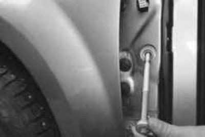
60. …and remove the bolts from the strut holes.
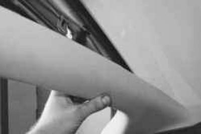
61. Remove the front pillar trims (see "Removing and installing interior trim").
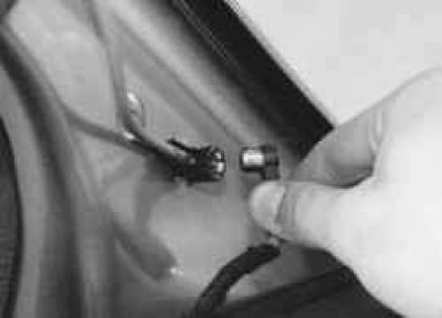
62. Disconnect the antenna wire from the terminal on the left front body pillar.
63. Loosen the two adjustable screw stops located at the ends of the instrument panel frame pipe…
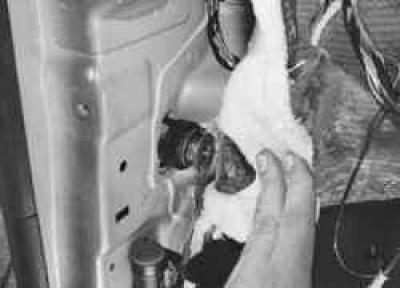
NOTE: Adjustable instrument panel frame stops are installed on the left and right side panels.
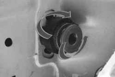
When removing the frame, loosen the clamping of the frame tube by turning the stop nuts counterclockwise. When installing the frame, first clamp the frame tube between the sidewalls by turning the stop nuts clockwise until the frame is fixed, and then secure the frame with bolts.
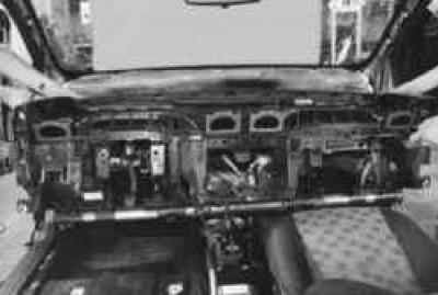
64. …make sure all wires are disconnected from the instrument panel frame and remove the frame.
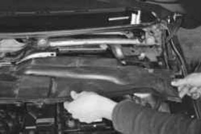
65. If it is necessary to replace the steering column mounting bracket, which also serves to secure the instrument panel frame, remove the air intake box grille and the water-diverting shield located underneath it (see "Removing and installing the air intake box grille and water drain shield")…
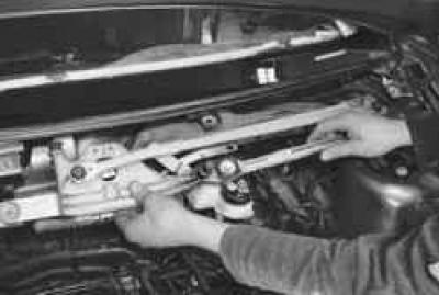
66. …and also the windshield wiper trapezoid assembled with the gear motor (see "Removing and installing the windshield wiper linkage assembly with the gear motor").
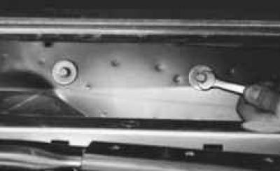
67. Remove the two bolts securing the bracket to the front shield…
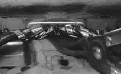
68. …disconnect the wire harness holder from the bracket…
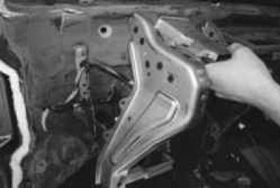
69. …and remove the bracket.
70. Install the parts in the reverse order of removal.
For details, please visit the website [FORDBOOK.ru]