


Location of screws for fastening the instrument panel and individual panel units
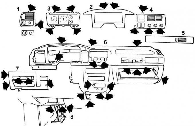
1 – left ventilation panel, 2 – decorative instrument cluster trim, 3 – instrument cluster, 4 – central ventilation panel, 5 – right ventilation panel, 6 – instrument panel, 7 – lower instrument panel panel, 8 – hood release handle
Cars manufactured before 04.1992
1. Remove the ground wire from the battery.
Attention! This will erase the information in the electronic storage devices.
2. Unscrew the four screws securing the decorative instrument cluster trim and remove it.
3. Unscrew the four instrument cluster mounting screws and move the instrument cluster forward slightly from the front panel.
4. Remove the multi-pin connector from the rear side.
Attention! The red connector of the graphic display has a stopper that must be pressed down first.
5. Disconnect the speedometer drive cable by moving the large locking ring securing the speedometer cable to the instrument cluster to the right.
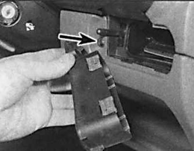
6. Remove the instrument cluster from the instrument panel (the arrow indicates the screw securing the upper part of the instrument panel, which can be accessed after removing the heater panel).
7. Remove the heater panel.
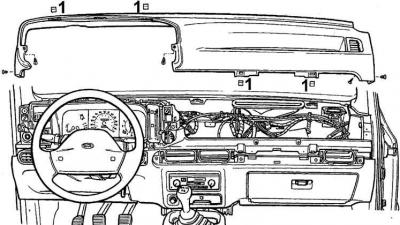
8. Remove the upper part of the instrument panel, which is secured with five screws and four clamps (1).
9. Using a strong tug, release the upper part of the instrument panel from the clips located directly behind the windshield.
10. Remove the soft upholstery mat on both sides under the instrument panel, which are secured with clips.
11. Remove the lower trim panel on the driver's side, which is secured with six screws. One of the screws can only be accessed after removing the fan grille. Remove the additional warning light bulb from the malfunction indicator module.
12. Disconnect the glove box levers and hinges. Remove the hinge pins and remove the cover.
13. Remove the auxiliary fuse box.
14. Remove the ABS and ESC/EEC unit. Unscrew the two nuts inside the glove compartment.
15. Remove the radio, ashtray, cigarette lighter panel and gear shift lever cover.
16. Remove the center console.
17. Remove the six screws securing the lower panel on the passenger side. Remove the panel.
18. Installation is carried out in the reverse order of removal.
Cars manufactured since 04.1992
1. Remove the ground wire from the battery.
Attention! This will erase the information in the electronic storage devices.
2. Unscrew the two screws and retaining clips securing the instrument cluster decorative trim and remove the glass.
3. Unscrew the four instrument cluster mounting screws and move the instrument cluster forward slightly from the front panel.
4. Remove the multi-pin connector from the rear side.
Attention! The red connector of the graphic display has a stopper that must be pressed down first.
5. Disconnect the speedometer drive cable by moving the large locking ring securing the speedometer cable to the instrument cluster to the right.
6. Remove the instrument cluster from the instrument panel.
7. Remove the center console.
8. Remove the radio.
9. Remove the steering wheel, the turn signal switch on the steering column and the windshield washer switch.
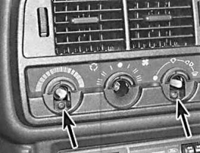
10. Remove the three rotary knobs (indicated by arrows) of the heater control unit by simply pulling them towards you in order to gain access to the two screws securing the heater control unit trim panel.
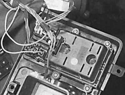
11. Unscrew the 4 screws securing the control unit cover, pull the cover slightly and disconnect the connectors. Completely remove the control unit cover.
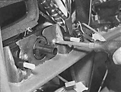
12. Unscrew the two screws securing the control unit cover. Remove the heater control unit and disconnect the multi-pin connector.
13. Press the holder at the bottom of the control knob and remove the light switch knob.
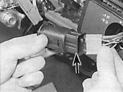
14. Remove the light switch (indicated by the arrow) from the panel and disconnect the connector.
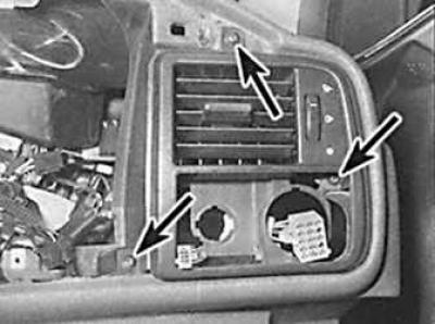
15. Unscrew the three screws (indicated by arrows) and remove the right ventilation panel from the instrument panel.
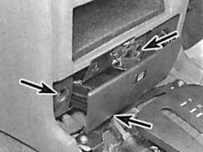
16. Remove the ashtray, unscrew the three screws (indicated by arrows) and remove the ashtray body, disconnecting the backlight lamp.
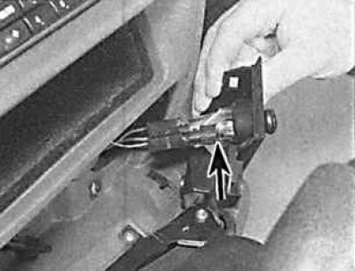
17. Unscrew the screw and, having disconnected the connector, remove the cigarette lighter (indicated by the arrow) from the instrument panel.
18. Remove the left and right lower panels under the instrument panel.
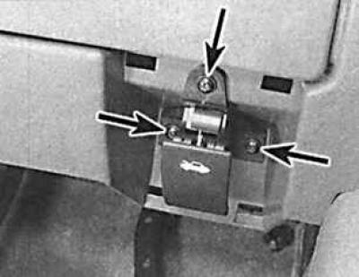
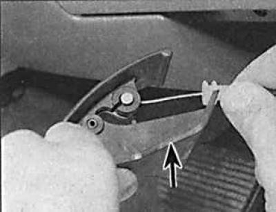
19. Unscrew the three screws (indicated by the arrows in the figure on the left) and remove the hood opening handle (indicated by the arrow in the figure on the right).
20. Remove the cable mounting clamp and disconnect the handle from the cable.
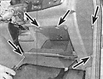
21. Unscrew the five mounting screws (indicated by arrows) of the lower right instrument panel and remove it.
22. Open the glove compartment.
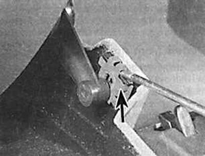
23. Use a screwdriver to remove the clamp (indicated by the arrow) and detach the hinge bracket.
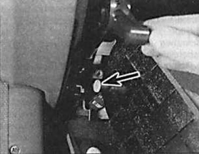
24. Remove the glove box from the instrument panel, marking the plastic bushings (indicated by the arrow) at the rotation points.
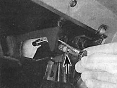
25. Remove the backlight lamp (indicated by the arrow), disconnect the connector and remove it.
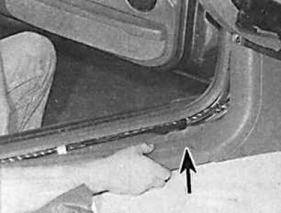
26. Remove the three screws securing the lower panel (arrow) on the passenger side and remove it.
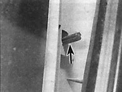
27. Hook the upper end of the left pillar trim panel until the clips (arrow) are released. Lift the panel to release the lower catch from the support and remove the panel. Repeat the same operation for the right panel.
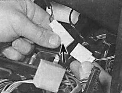
28. Disconnect the connector (indicated by the arrow) of the hazard warning LED through the opening for the instrument cluster.
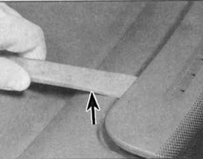
29. Carefully pry the windshield ventilation panel (arrow) away from the top of the instrument panel to access the upper instrument panel mounting screws.
 |
 |
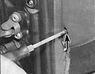
30. Unscrew the screws (indicated by arrows) securing the instrument panel (on the left – the left screw securing the panel, on the right – the upper screw securing the panel).
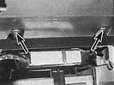
31. Unscrew the nuts (indicated by arrows) securing the instrument panel and partially remove it.
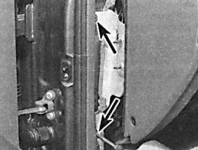
32. Move the instrument panel to access the two screws (indicated by arrows) securing the support suspension.
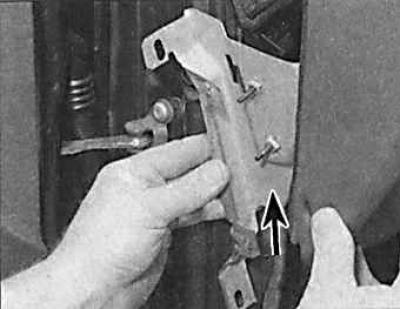
33. Unscrew the two screws of the support bracket (indicated by the arrow) on the left side of the instrument panel and remove the bracket.
34. Check that all instrument panel mounting clamps and screws have been removed and remove the instrument panel.
35. Installation is carried out in the reverse order of removal.