You will need: TORX T25 wrench, sockets «on 10», «at 13», screwdrivers with Phillips and flat blades.
1. Disconnect the wire from the terminal «minus» battery.
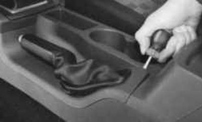
2. Pry off the edge of the frame of the parking brake lever cover with a screwdriver..
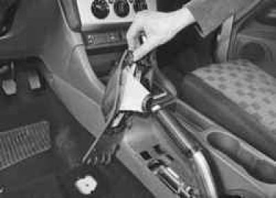
3.... disconnect the frame from the lining of the floor tunnel, overcoming the elastic resistance of its latches, and remove the cover from the lever.
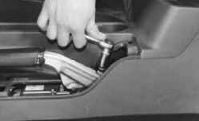
4. Fully unscrew the locknut and adjusting nut to the very end of the threaded lug of the front parking brake cable.
NOTE: Disconnecting the front parking brake cable from the lever is necessary in order to raise the actuator lever to its maximum height. Otherwise, it will not be possible to remove the lining of the floor tunnel from the lever.
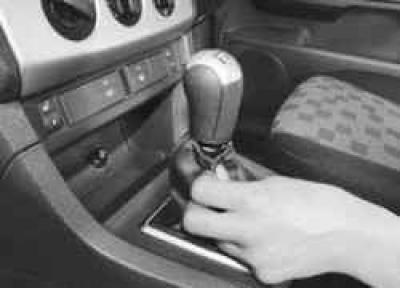
5. Remove the cover from the gear lever handle..
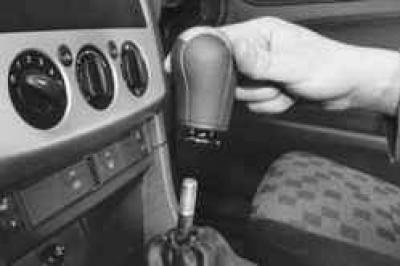
6.... and unscrew the handle from the threaded shank of the lever.
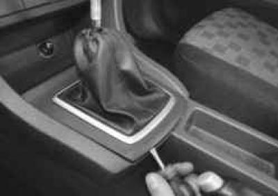
7. Pry off the edge of the frame of the gear lever cover with a screwdriver..
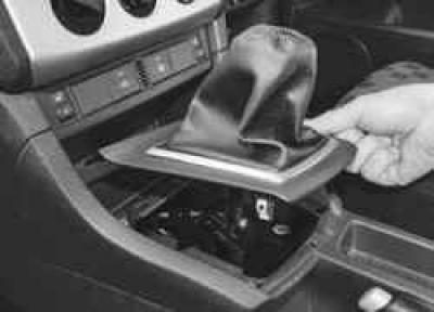
8.... disconnect the frame from the lining of the floor tunnel, overcoming the elastic resistance of its latches, and remove the cover from the lever.
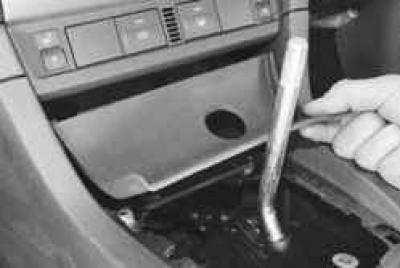
9. Remove the decorative overlay of the instrument panel console, overcoming the elastic resistance of its holders.
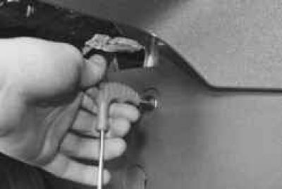
10. Turn out the top screw of fastening of the left part of facing of a tunnel of a floor.
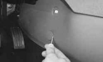
11. Using a screwdriver, remove the decorative cap of the lower screw securing the left side of the floor tunnel lining..
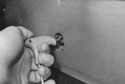
12.... remove the screw..
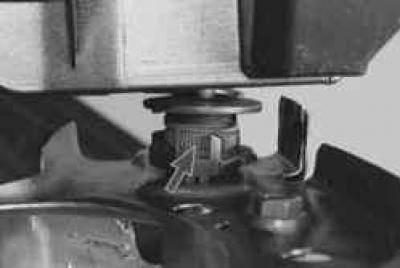
13.... and remove the left side of the lining by sliding it forward to remove the clips from under the edge of the middle part.
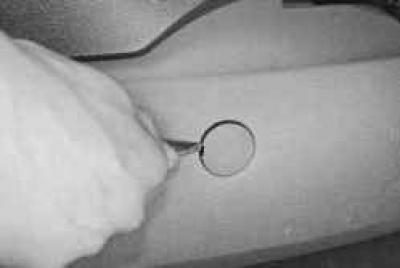
14. Prying with a screwdriver, remove the decorative cap of the screw securing the right side of the floor tunnel lining..
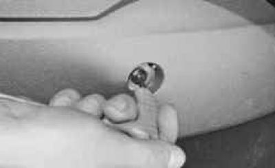
15.... remove the screw..
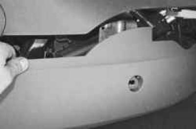
16.... and remove the right side of the lining by sliding it forward to remove the clips from under the edge of the middle part.
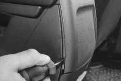
17. Prying off the edge of the rear decorative lining of the floor tunnel lining with a screwdriver..
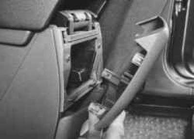
18.... remove the pad, overcoming the elastic resistance of its latches.
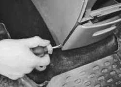
19. Prying off the bottom corner of the glove box for passengers in the rear seat with a screwdriver..
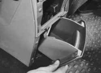
20.... remove the box from the nest of the floor tunnel lining, overcoming the elastic resistance of its spring holders.
NOTE: An ashtray can be fitted instead of the glove box as an option.
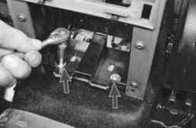
21. Turn out two bolts of back fastening of an average part of facing of a tunnel of a floor to the basis of a body …
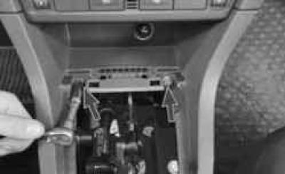
22.... two bolts of the front fastening of the lining to the instrument panel..
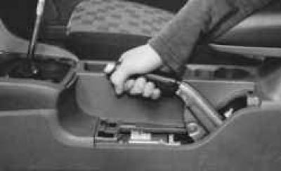
23.... raise the parking brake lever to the maximum possible height..
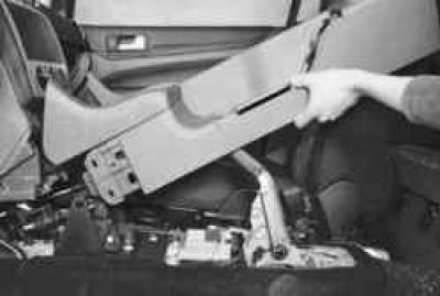
24.... and remove the middle part of the floor tunnel lining by moving it up and forward along the parking brake lever.
25. Install the parts in the reverse order of removal.
26. Adjust parking brake actuator (cm. «Parking brake actuator adjustment»).
Visitor comments