Warning: To avoid injury, before working on the engine with the hood open, check the fan for cracks or damage. Do not attempt to repair a fan with damaged blades - replace it.
Description
1. The electric motor wires are connected in such a way that it operates only when the ignition is on.
Warning: Before doing anything under the hood, turn off the electric fan, as it may run with the ignition left in the "on" position, even if the engine is not running.
2. When the vehicle is moving, the operation of the electric fan is controlled by the integrated control relay and the EEC-4 module, which powers the electric fan under the following conditions:
a) when the engine temperature is above normal (the moment of switching on falls within the temperature range of 102.5-99.7 degrees Celsius (215-210 degrees Fahrenheit)), the fan rotates at low speed. It also switches on when the air conditioner is running, when the vehicle speed does not provide sufficient natural air flow (this effect occurs at speeds from 69 to 77 km/h (43 to 48 mph)).
b) turns off the high speed fan (except on four-cylinder engines with manual transmission) if the engine temperature is above optimum and the fan speed is low (on at 110.9 degrees Celsius (230 degrees Fahrenheit), off at 107.5 degrees Celsius (224 degrees Fahrenheit)).
v) turns off the fan (if the engine coolant temperature is not too high), if the throttle is open (fuel consumption is high) and/or the air conditioning is not too loaded.
Examination
3. A full test of this system is not possible because the electric fan motor is switched on by the integrated control relay, which in turn is controlled by the EEC-IV system.
However, some elements can be checked.
4. Remove the fan motor electrical connector and place it at the rear of the motor. Remove the plug and make sure there is no corrosion on the plug or terminal. Insert the electrical connector and make sure it is securely installed.
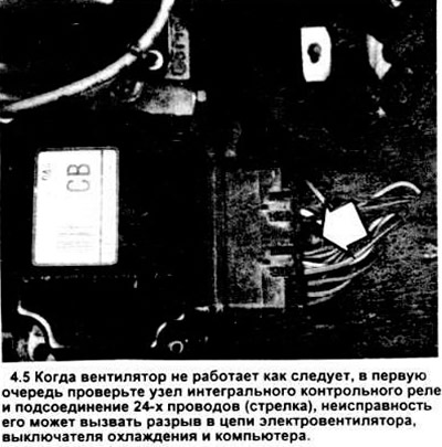
5. Remove the radiator shield (plastic protector with VECI label on it), make sure that the 24-wire integrated control relay module connector (see picture) is connected securely (it is held on by one small bolt that should be tight).
6. Check the wires between the integrated control relay module and the fan, make sure they are in good condition. If they are split or broken, repair them.
7. Using a tester, measure the electrical conductivity between the terminals of the engine cooling thermal switch. Warm up the engine and allow the coolant temperature to reach its operating value. When the coolant heats up, the resistance at the terminals of the cooling thermal switch should drop to almost zero and the electrical circuit supplying current to the fan motor is connected.
a) if the resistance at the terminals of the thermal switch does not drop when the coolant heats up, then the switch is faulty. Replace it.
b) if the resistance at the terminals decreases (when the electric fan circuit is closed), then the switch is OK and the fan can work.
8. When the fan motor does not work, it may be faulty. Remove the motor electrical connector, connect a pair of wires with alligator clips and fuses to the terminals of the electric fan and battery. If the electric fan does not work, replace it.
9. If the fan works when connected to the battery, then consider these other options.
a) there is a break in the circuit somewhere between the switch, the computer, the control relay and the electric motor, in this case the problem is solved by testing with a test light or tester.
b) if the circuit check does not yield anything, then the problem is either in the integrated control relay or in the computer itself.
Replacement of elements
10. Disconnect the negative battery cable.
11. Unscrew the screws and detach the radiator screen. Place the integrated relay assembly on top of the radiator stand. Unscrew the remaining bolt and remove the electrical connector (see Figure 4.5), then remove the control assembly.
12. Pull out the fan motor electrical connector.
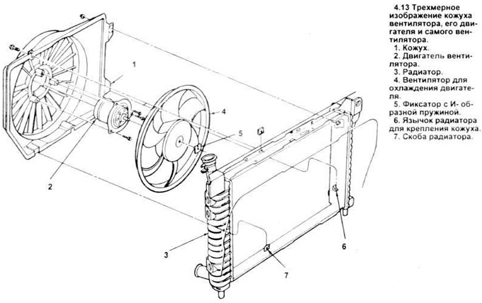
13. To remove the fan and shroud from the radiator, unscrew the nut in the upper left corner of the shroud and the bolt in the upper right corner (see figure), then remove the fan and shroud from the mounting tabs on the radiator.
Note: This assembly may need to be rotated slightly when removed from the engine.
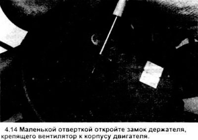
14. Place the fan and casing on a workbench with the fan on top. Use a small screwdriver to unscrew the holders from the motor stand (see picture) and remove the fan.
15. Remove the three fan motor mounting bolts and remove the motor from the housing assembly.
16. Installation is carried out in the reverse order of disassembly.
(For more information, please visit the website: www.FordBook.ru)