Contents: Light switch, heater fan switch ↳ Instrument lighting controller ↳ Mirror position control switch and… ↳ Direction indicator switch and… ↳ Individual lighting switch on the… ↳ Reverse Light Switch (Manual… ↳ Sunroof opening switch ↳ Handbrake switch ↳ Brake light switch ↳ Oil pressure sensor ↳ Rear Window Defogger Switch ↳ Front seat adjustment switch ↳ Central locking system engine ↳ Window lifter drive motor ↳ Seat position adjustment motor, seat… ↳ Seat back tilt motor ↳ Hatch drive electric motor ↳ Speedometer sensor ↳ Fuel computer illumination lamp ↳ Fuel flow sensor (carbureted models… ↳
Light switch, heater fan switch
1. Remove the ground wire from the battery.
2. Remove the switch handle by pulling it towards you.
3. Press the two latches and remove the switch from the dashboard.
4. Disconnect the connector and remove the switch.
5. Installation is carried out in the reverse order of removal.
Instrument lighting controller
1. Unscrew the four screws and remove the instrument cluster trim.
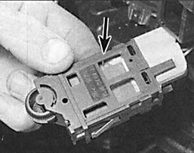
2. Remove the instrument lighting controller (indicated by the arrow) and disconnect the connector.
3. In case of malfunction, the instrument lighting regulator is not repaired but must be replaced.
Mirror position control switch and power window switch
1. Use a thin-bladed screwdriver to pry the switch out of the armrest.
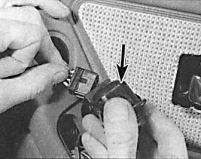
2. Disconnect the connector and remove the switch (indicated by the arrow).
3. Installation is carried out in the reverse order of removal.
Direction indicator switch and windshield wiper/washer switch
1. Remove the ground wire from the battery.
2. Remove the steering wheel center trim.
3. Remove the upper and lower steering column covers, first unscrewing the six mounting screws.
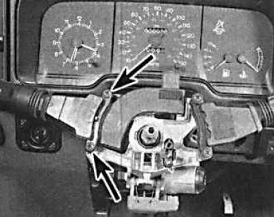
4. Unlock the steering wheel and turn it so that you can access the two screws (indicated by arrows) securing the switch. Unscrew the screws.
5. Remove the switch from the steering column and disconnect the connector.
6. When installing, check the switch operation before installing the steering column covers and steering wheel center cover.
Individual lighting switch on the door pillar
1. Unscrew one screw and remove the switch.
2. Secure the wires with a thread or clothespin so that they do not fall inside the rack, and then disconnect the connector.
3. Before installation, lubricate the pivot point of the switch button with technical petroleum jelly.
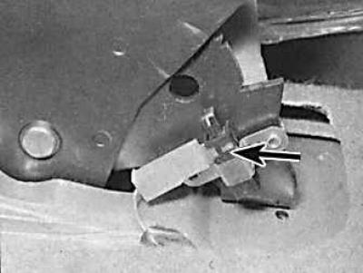
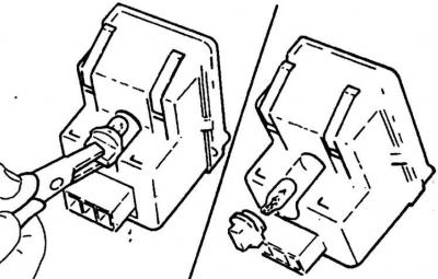
Reverse Light Switch (Manual Transmission)
The reverse light switch is located on the right side of the gearbox.
1. Raise and secure the front of the vehicle on stands.
2. Remove the wire from the switch, thoroughly clean the switch and the area adjacent to the switch, and unscrew the switch.
3. After installing the switch, check that the switch wire is located at a sufficient distance from the exhaust pipe.
Sunroof opening switch
1. Using a thin-bladed screwdriver, carefully pry the switch out of the overhead console.
2. Disconnect the connector and remove the switch.
Handbrake switch
1. Remove the rubber boot and, if necessary, the center console or sensor trim panel.
2. Remove the wire from the sensor.
3. Unscrew the two screws and remove the sensor.
Brake light switch
1. Remove the trim under the instrument panel on the driver's side, secured with plastic clips.
2. Remove the wires from the switch.
3. Turn the switch 90° counterclockwise and remove it from the brake pedal mounting bracket.
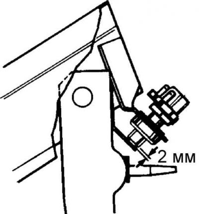
4. When installing, press the pedal all the way down, insert the switch and turn it clockwise to lock it in place. Release the pedal and check that at least 2 mm of the switch rod is visible.
Oil pressure sensor
The oil pressure sensor on all engines except DOHC is located on the left side of the cylinder block. On DOHC engines, the oil pressure sensor is located on the front left side of the cylinder block.
1. To facilitate access to the sensor, move one of the pipelines to the side.
2. Remove the wires from the switch.
3. Unscrew and remove the sensor.
4. Before installation, thoroughly clean the sensor and its socket. Apply a thin layer of sealant to the sensor thread.
5. Install the sensor, connect the wires, start the engine and check the tightness of the sensor installation.
6. Stop the engine and check the engine oil level.
Rear Window Defogger Switch
1. Unscrew the four screws and remove the instrument cluster trim.
2. Using a thin screwdriver blade, carefully pry the switch out of its socket.
3. Remove the connector from the switch.
Front seat adjustment switch
1. Remove the seat trim panel.
2. Use a thin-bladed screwdriver to remove the control handles from the switch.
3. Unscrew the two mounting screws, remove the switch and disconnect it.
Central locking system engine
Central door locking system
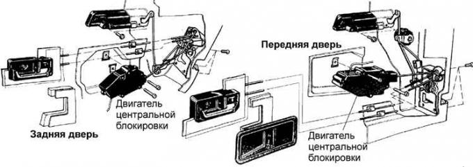
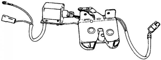
Rear door lock with electromagnet
1. Remove the ground wire from the battery and open all doors.
2. Remove the inner door trim.
3. Carefully remove the door insulating covering from the door in the area where the central locking system motor is installed.
4. Unscrew the two screws (indicated by arrows) securing the engine and disconnect the engine from the lock control rod.
5. Remove the electrical connector.
6. Remove the electric motor. If the motor is faulty, it must be replaced as it cannot be repaired.
7. Installation is carried out in the reverse order of removal, and it is necessary to set the door lock button to the "open" position, loosen the screw securing the inner handle, move the handle forward until it stops and tighten the screw.
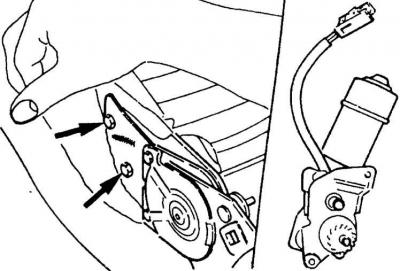
Window lifter drive motor
1. Remove the window lifting mechanism together with the motor.
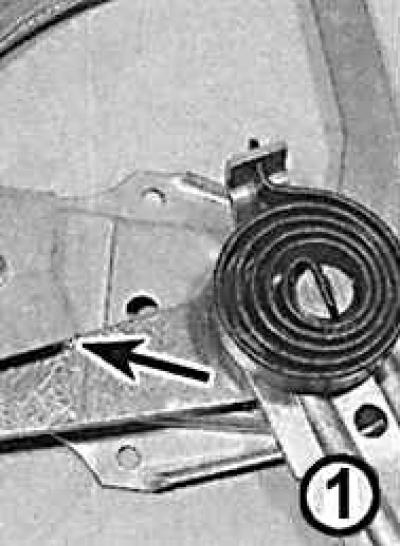
2. Check that the spring holds the lever in the end position (arrow).
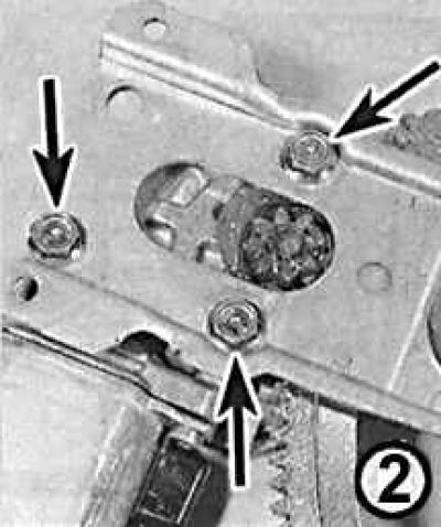
3. Unscrew the three bolts (indicated by arrows) and separate the motor from the glass lifting mechanism.
Caution! Careless release of the spring may cause damage and injury.
4. Installation is carried out in the reverse order of removal.
Seat position adjustment motor, seat cushion lift and movement motors
1. Move the front seat back as far as it will go.
2. Unscrew the two mounting bolts from the front of the seat frame and tilt the seat back.
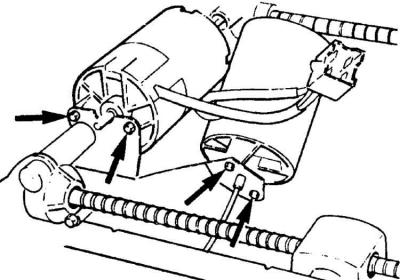
3. Unscrew two bolts (indicated by arrows) and remove the electric motors.
4. Check that the drive cables from the worm gears move without effort, otherwise also disconnect one end of the worm gear.
5. If removing only one motor, remove its blade contacts from the common connector after removing the connector housing.
6. Installation is carried out in the reverse order of removal.
Seat back tilt motor
1. Remove the front seat.
2. Unscrew the two mounting bolts, disconnect the connector and remove the electric motor from the deflection mechanism.
3. Install the motor so that the gear of the electric motor meshes with the gear of the deflection mechanism.
4. Connect the connector and secure the electric motor with two bolts.
5. Further installation is carried out in the reverse order of removal.
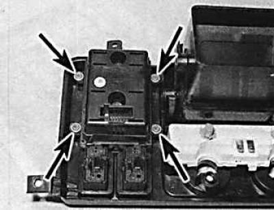
Hatch drive electric motor
1. Remove the upper console.
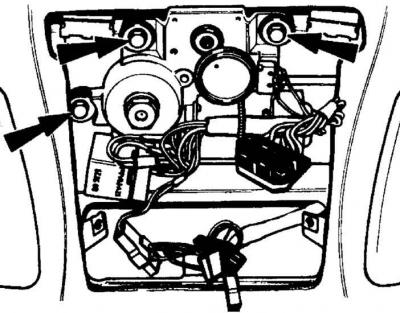
2. Unscrew the three mounting bolts (indicated by arrows), lower the electric motor, disconnect the connector and remove the relay.
3. Install the engine so that the toothed gear of the electric motor meshes with the gear of the hatch cover position control mechanism.
4. Install the relay, connect the connector and secure the electric motor with three bolts.
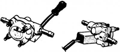
Speedometer sensor
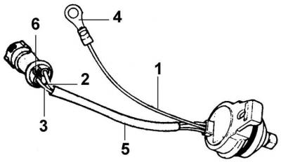
1 – brown wire, 2 – brown wire with a yellow stripe, 3 – brown wire with a black stripe, 4 – ground contact, 5 – insulating tube, 6 – place where the brown wire is cut
The speedometer is driven by an electric sensor located on the left side of the gearbox extension.
1. Raise and secure the front of the vehicle.
2. Place a suitable container under the sensor.
3. Unscrew the mounting bolt (indicated by the arrow) and remove the sensor from the gearbox (1 – manual gearbox, 2 – automatic gearbox).
4. Disconnect the electrical connector.
5. When installing a new sensor, install the drive gear and ring clamp from the old sensor, and on models with an automatic transmission, also the sealing ring.
6. If the old sensor had two wires and the new one has three, cut the brown wire from the connector and additionally install grounding.
7. Install the new sensor and secure it with a new bolt (M6x25mm for manual transmission and M6x35mm for automatic transmission). In addition to the new sensor, the bolt also secures the new grounding lug, radio grounding busbar, and connector mounting bracket.
8. Connect the connector and secure it to the bracket.
9. Bring the oil level in the gearbox up to normal.
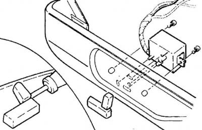
Fuel computer illumination lamp
Cars manufactured before 04.1992.
1. Remove the decorative cover of the instrument panel, which is secured with four screws.
2. Carefully remove the fuel computer. Remove the connector by pressing it down.
3. Remove the socket with the bulb by squeezing it with pliers and turning it counterclockwise. Pull the old bulb out of the socket.
4. The installation of a new light bulb is carried out in the reverse order of removal.
Cars manufactured since 04.1992.
5. Remove the decorative cover of the instrument panel, which is secured with two screws and two clamps.
6. Remove the instrument dimmer and disconnect the connector.
7. Remove the three heater control knobs to access the heater panel mounting screws.
8. Unscrew the four screws securing the heater panel and partially move the panel.
9. Disconnect the glass heater and fuel computer connectors from the panel and remove the panel.
10. Unscrew the four screws (indicated by arrows) securing the computer to the panel and remove the computer.
11. Replace the fuel computer backlight lamps.
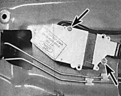
Fuel flow sensor (carbureted models only)
The sensor is located on the left mudguard in the engine compartment.
1. Remove the ground cable from the battery.
2. Remove the electrical connector and fuel lines from the sensor.
3. Unscrew the three screws securing the sensor bracket. Remove the sensor together with the bracket.
4. The sensor is installed in the reverse order of removal.
[A copy of the article is available on the website FordBook.ru]