Contents: Removing and installing the vacuum… ↳ Removing and installing the intake… ↳ Removing and installing the fuel… ↳ Removing and installing the speed… ↳ Installing and removing the voltage… ↳
Removing and installing the vacuum sensor in the suction line
Disconnect the ground wire from the battery clamp.
Remove the multi-pin connector plug from the sensor (Fig. 2.141).
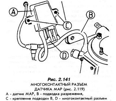
Remove the vacuum tube.
Unscrew the sensor.
The sensor is installed in the reverse order.
Removing and installing the intake air temperature sensor
Disconnect the ground wire from the battery clamp.
Remove the multi-pin connector plug from the sensor.
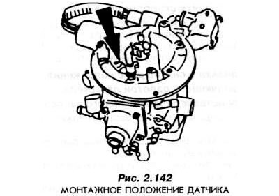
Unscrew the sensor from the CFJ device (Fig. 2.142).
The sensor is installed in the following order:
Lubricate the sensor threads with silicone sealing paste.
Screw in the sensor and tighten to the specified torque.
Insert the multi-pin connector plug into the sensor socket.
Connect the battery to the vehicle's electrical system.
Removing and installing the fuel pump safety switch
Disconnect the ground wire from the battery clamp.
Unscrew the trunk lid and find the switch inside.
Remove the multi-pin connector plug.
Remove the switch. It is installed in the reverse order.
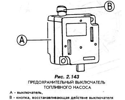
Pay particular attention to the correct connection of the connector and its careful closing. Check the operation and restoration of the switch by pressing the button (B, Fig. 2.143) twice.
Removing and installing the speed sensor
Unscrew the nut installed on the drive cable and disconnect the speedometer drive (Fig. 2.144).
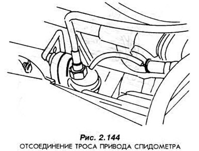
Unscrew the sensor from the gearbox. Install the new sensor in reverse order.
Installing and removing the voltage relay, engine control device and fuel pump relay
Disconnect the ground wire from the battery clamp.
Remove the fuse box cover.
Remove the floor trim.
Unscrew the three bolts securing the fuse box (Fig. 2.145).
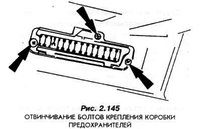
Remove the fuse box by tilting it downwards.
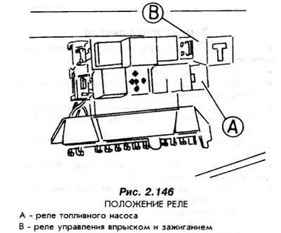
Replace the damaged relays (Fig. 2.146). Install the fuse box in place.
(The original post is on the web portal: FordBook)