Note: See warning in paragraph 1 this chapter.
Coolant Temperature Gauge Sensor
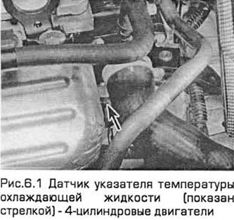
1. On 4-cylinder engines, the sensor is installed on the thread in the left end of the block head (see fig.6.1).
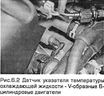
2. On V-shaped 6-cylinder engines, the sensor is installed on the engine on the left in front of the bypass circuit housing (see fig.6.2).
Examination
3. If the temperature gauge does not work, check the fuses first (chapter 12).
4. If the pointer is constantly in the sector "Hot" (hot), when troubleshooting the cooling system, refer to "troubleshooting" at the end of this guide.
5. If the pointer arrow points to "Hot" almost immediately after starting a cold engine, disconnect the coolant temperature gauge sensor harness connector. If the reading drops sharply after this, replace the sensor. If the reading remains high, then it is possible that the pointer wire is shorted to ground or the pointer itself is faulty.
6. If the indicator shows a malfunction after the engine warms up (in about 10 minutes), and the fuse is good, stop the engine. Disconnect the sensor wiring connector and use the auxiliary wire to connect the white/red wire to ground (on engine, on uncoated metal). If the pointer then points to a sector "Hot", replace the sensor.
7. If after that the pointer does not work, then it is possible that its circuit is open or the pointer itself is faulty. Details are in chapter 12.
Withdrawal
8. Empty the cooling system (Chapter 1).
9. On 4-cylinder models, remove the resonator support bracket bolts from the engine compartment front cross member. Loosen the screws of the two clamps that secure the resonator to the air flow meter and prechamber hoses. Then move the resonator away from the thermostat housing (chapter 4A).
10. On models with V-shaped 6-cylinder engines, remove the cover of the cooling pump drive belt. Remove the intake duct from the air cleaner (chapter 4A). Battery can be removed for better access (chapter 5A).
11. On models with 4-cylinder engines, disconnect the expansion tank hose and upper radiator hose from the outlet pipe of the thermostat housing. Then disconnect the metal pipe/coolant hose from the thermostat.
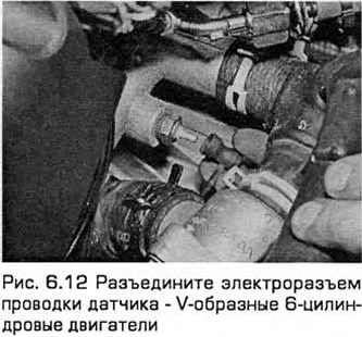
12. Disconnect the sensor wiring connector (see fig. 6.12).
13. Turn out the gauge and remove it.
Installation
14. Clean the hole in the thermostat housing as thoroughly as possible. Then apply some sealant to the sensor threads. Screw in the sensor and tighten it to the required torque, and then connect the electrical connector of its wiring.
15. Attach hoses and install removed components. Add liquid to the cooling system (Chapter 1). Start the engine. Control the absence of leaks and the operation of the pointer.
Coolant temperature sensor
16. The difference between the coolant temperature sensor and the pointer sensor is that it provides data to the engine management system. The same data is used to determine when the radiator fan turns on.
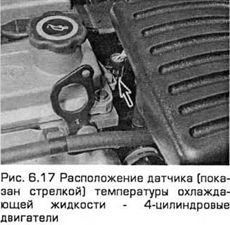
17. On 4-cylinder engines, the sensor is mounted on a thread on the top of the thermostat housing (see fig.6.17).
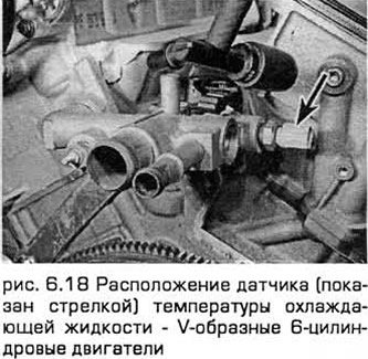
18. On V-shaped 6-cylinder engines, the sensor is installed on the engine on the left in the rear of the bypass circuit housing (see fig.6.18).
Examination
19. Disconnect the negative battery cable (chapter 5, paragraph 1).
20. On 4-cylinder engines, remove the resonator support bracket bolts from the front cross member of the engine compartment. Loosen the screws of the two clamps that secure the resonator to the air flow meter and prechamber hoses. Then move the resonator away from the thermostat housing (chapter 4).
21. On V-shaped 6-cylinder engines, access to the sensor is difficult. To improve access, remove the intake duct from the air cleaner and the air cleaner itself (chapter 4A). Move the sensor wiring to the side.
22. Disconnect the sensor electrical connector.
23. Using an ohmmeter, measure the resistance between the sensor terminals. Depending on the temperature of the sensor probe, the measured resistance may have different values, but within the limits specified in the Technical Requirements. If you change the temperature of the sensor by removing it (see below) and placed in a refrigerator for a while or a little heating, the resistance should change accordingly.
24. If the readings do not change, then the sensor is faulty and needs to be replaced.
25. Finally, connect the electrical connector and install the removed components.
Withdrawal
26. Disconnect the negative battery cable (chapter 5, paragraph 1).
27. On 4-cylinder engines, it is not necessary to drain the liquid from the cooling system, which must first cool down. When the engine is completely cool, remove the expansion tank filler cap to relieve pressure in the system, and then install the cap. If you work carefully and plug the hole as soon as you unscrew the sensor, the loss of coolant will be minimal. This eliminates the procedure for draining the liquid from the cooling system, which, otherwise, must be performed (Chapter 1).
28. On V-shaped 6-cylinder engines, drain the liquid from the cooling system (Chapter 1).
29. Provide access to the sensor as indicated in subparagraph "Examination" (see above).
30. Turn out the gauge and remove it. If you did not drain the liquid from the cooling system, then you need to immediately plug the hole that has formed.
Installation
31. Clean the sensor hole as thoroughly as possible from the sealant. Then apply some sealant to the sensor threads. Screw in the sensor and tighten it to the required torque, and then connect the electrical connector of its wiring.
32. Attach the hoses and install the removed components. Add liquid to the cooling system (Chapter 1). Start the engine. Check for leaks.
Minimum coolant level sensor
Examination
33. This sensor (with plate contact) installed at the bottom of the expansion tank of the cooling system and is activated by a float containing a magnet. If the coolant level drops to the MIN·mark or below, the corresponding indicator on the front panel lights up.
34. If the indicator light does not come on within the five second light bulb test, check the light bulb and replace it if necessary as instructed in chapter 12.
35. To check the sensor itself, disconnect it with an electrical connector and measure the resistance at its terminals with an ohmmeter. When the float is raised, the resistance should be 90 ohms, when it is lowered - 150 kOhm.
36. If the readings differ significantly from those indicated above, the sensor is defective and must be replaced.
37. If the sensor and the bulb are working, then the malfunction may be caused by wiring or an additional display unit (chapter 12).
Withdrawal
38. Disconnect the negative battery cable (chapter 5 paragraph 1).
39. Remove expansion tank (paragraph 7).
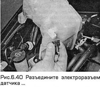
40. Disconnect the sensor connector (see fig.6.40).
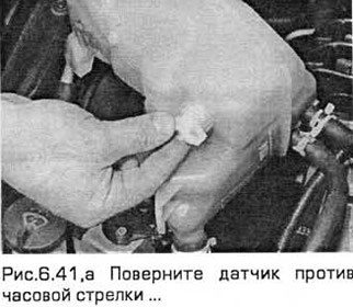
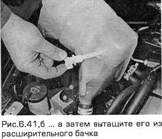
41. Turn the sensor counterclockwise and then pull it out (see fig. 6.41, a, b).
Installation
42. Installation - in the reverse order of removal. Recharge the cooling system (Chapter 1). Start the engine and after it is fully warmed up, check for coolant leaks.
Visitor comments